December 2005 © TOSHIBA TEC e-STUDIO163/203 POWER SUPPLY UNIT
7 - 3
7
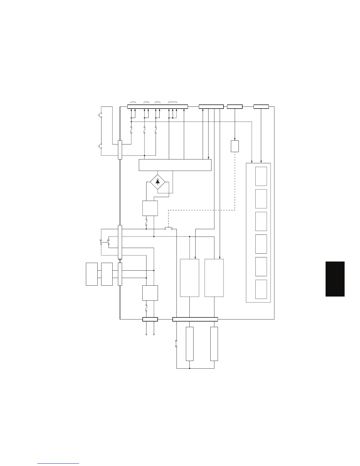
7.3 Configuration of Power Supply Unit
Fig. 7-1
PWRDWN-1
PWRSV-1A MAIN board
MAIN board
+5VB
+5V
MAIN board,
FUS board
MAIN board
MAIN board
MAIN board
MAIN board
MAIN board,
PFU (via MAIN board)
MAIN board
+24VCOV-OFF
+24V
F201
ADF (via MAIN board)+24VDF
F202
F101
HTON1B
HTON2B
MAIN board
High-voltage
control signals
F203
Side heater lamp
control circuit
(TRC2)
High-voltage output circuit
OUT1
Needle electrode
bias
OUT2
Grid bias
OUT3
Developer bias
OUT4
Transfer bias
OUT5
Separation bias
OUT6
Transfer
guide bias
Center heater lamp
control circuit
(TRC1)
Main switch
ADU cover opening/closing
interlock switch
Front cover opening/closing
interlock switch
Fuser thermostat
Live
Neutral
Switching regulator
CN102 CN103
CN106
CN104 CN113 CN105
CN107
CN101
Noise
filter
Center heater lamp
Side heater lamp
FUS board
Damp heater
Noise
filter
125V-15A
200V-8A
125V-4A / 200V-4A
125V-4A / 200V-4A
125V-4A / 200V-4A
125V-6.3A
200V-4A
F102
Regulator
Relay
HTRRLYOFF-0
CN108
06/04
 Loading...