December 2005 © TOSHIBA TEC e-STUDIO163/203 ERROR CODE AND SELF-DIAGNOSTIC MODE
2 - 3
2
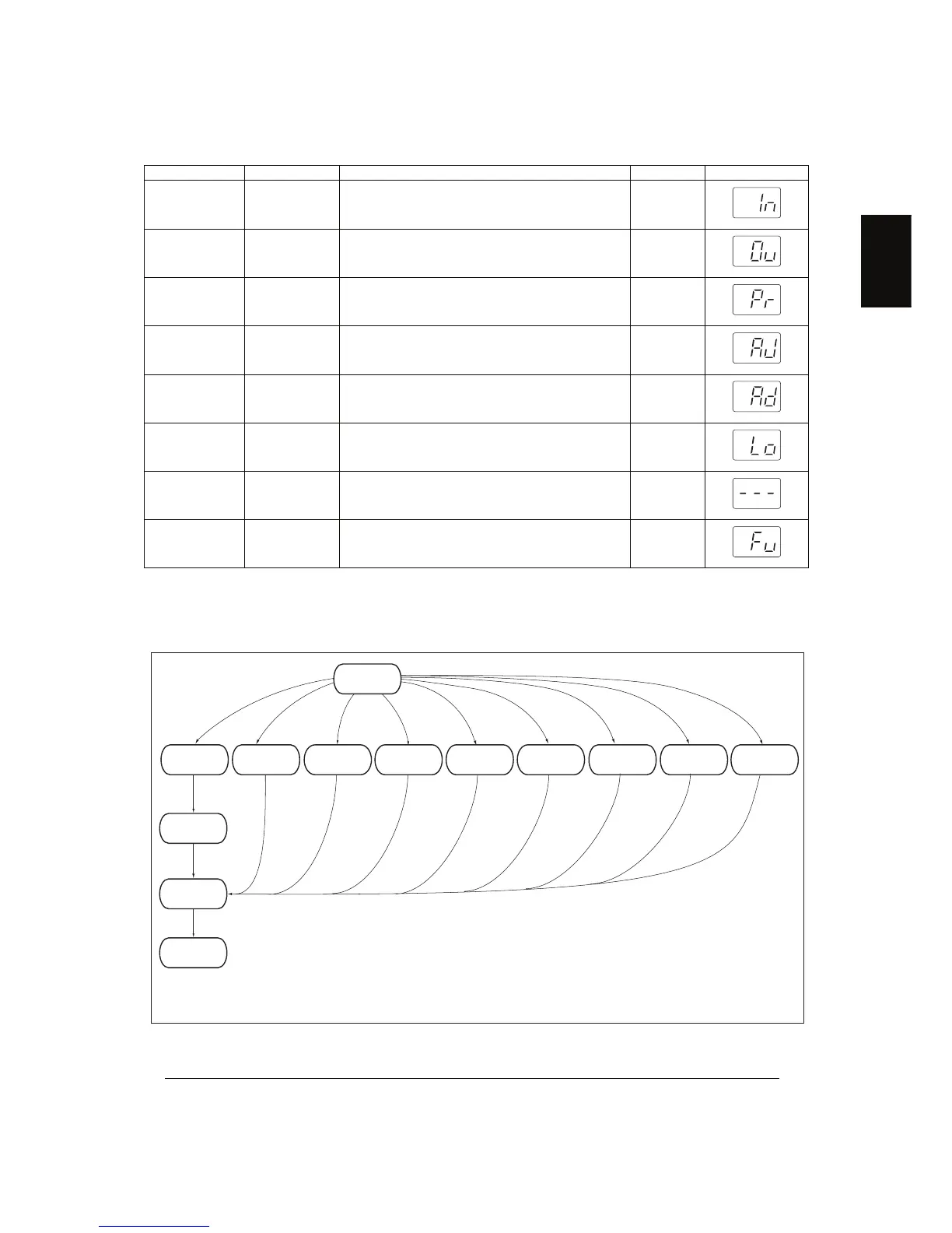
2.2 Self-diagnosis Modes
Note: Note:
To enter the desired mode, turn ON the power while two digital keys designated to each mode
(e.g. [0] and [5]) are pressed simultaneously.
Fig. 2-1
*1 Turn OFF the power after using the self-diagnosis modes, and leave the equipment to the user.
Mode For start Contents For exit Display
Input check
mode
[0]+[3]+
[POWER]
Checks the status of input signals. [POWER]
OFF/ON
Output check
mode
[0]+[4]+
[POWER]
Checks the status of output signals. [POWER]
OFF/ON
Test print
mode
[0]+[7]+
[POWER]
Outputs the test patterns. [POWER]
OFF/ON
Adjustment
mode
[0]+[5]+
[POWER]
Adjusts various items. [POWER]
OFF/ON
Setting mode [0]+[8]+
[POWER]
Sets various items. [POWER]
OFF/ON
List print mode [9]+[START]
+[POWER]
Prints out the data lists of the codes 05/08 and
pixel counter.
[POWER]
OFF/ON
Access code
mode
[8]+[START]
+[POWER]
Registers / deletes the access code. [POWER]
OFF/ON
Function set-
ting mode
[1]+[*]+
[POWER]
Sets the function table. [POWER]
OFF/ON
Warming up
Output check
mode
Input check
mode
Adjustment
mode
Setting
mode
List print
mode
Access code
mode
Function
setting mode
[POWER]
ON
Normal
Ready
[POWER]
OFF
To user
*1
[0][3] [0][4]
Test print
mode
[0][7] [0][5] [0][8] [1][*][9][START] [8][START]
State transition diagram of self-diagnosis modes
 Loading...