15
March 2005 © TOSHIBA TEC e-STUDIO520/600/720/850 EXIT/REVERSE SECTION
15 - 9
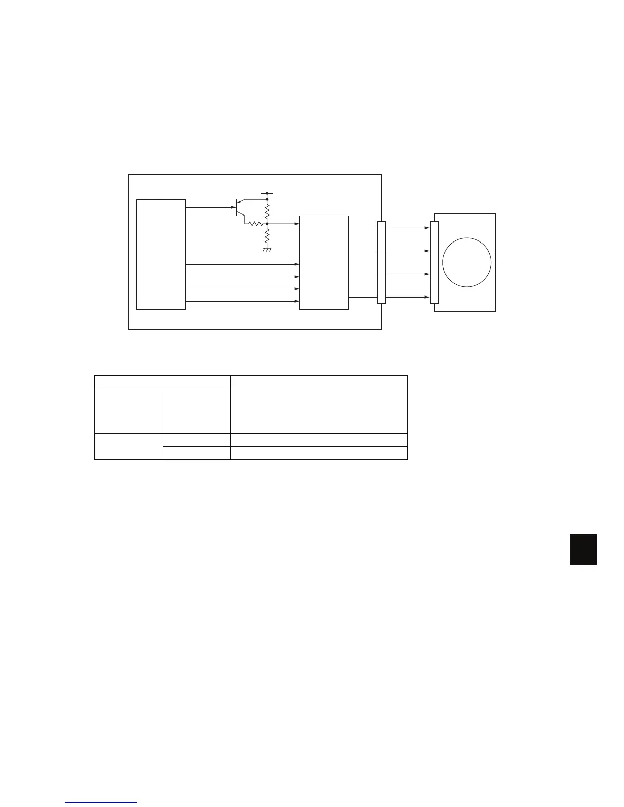
15.5 Exit motor control circuit
The exit motor is a stepping motor driven by the control signal output from the PFC CPU on the LGC
board and rotates the exit roller.
The PFC CPU outputs each phase signal (EXTMA-0, EXTMB-0, EXTMC-0, EXTMD-0) to the motor
driver. The motor driver converts this phase signal into a +24 V pulse signal (EXTMA-0A, EXTMB-0A,
EXTMC-0A, EXTMD-0A) and outputs it to the motor. Also, the rotation speed of the motor can be
switched by changing the output timing of each pulse signal.
Fig.15-6
Exit motor drive signal
Signal
Motor status
EXTMA-0
EXTMB-0
EXTMC-0
EXTMD-0
EXMVR-0
Pulse signal L Rotation when accelerating/decelerating
H Rotation at a constant speed
IC57
PFC CPU
EXTMB-0
EXTMA-0
Exit motor
EXTMC-0
EXTMD-0
EXTMB-0A
EXTMA-0A
EXTMD-0A
EXTMC-0A
IC83
Motor driver
LGC board
EXMVR-0
Q57
SG
+5.1VC

 Loading...


