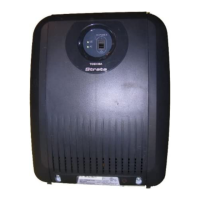
Strata CTX670 Installation
3-27
Strata CTX I&M September 2002
Cabinet Floor Mounting
The part numbers and descriptions of the floor mounting hardware are shown in Table 3-3.
Floor Mounting One or Two Cabinets
1. Remove front, side, and top covers from cabinet(s) (Figure 3-5). Remove plastic locating parts
from all cabinet back covers using a Phillips screwdriver.
2. Make sure that cabinet power supplies (BPSU672A) are installed per “Install Power Supply” on
Page 3-6.
3. If installing just one or two cabinets, install the BFIF fixtures on each side of the bottom of the
cabinet (Figure 3-15) and place the cabinet where it should be installed.
4. Set the bottom cabinet on the floor or mount surface, then set the top cabinet on the bottom
cabinet.
5. Fasten the two cabinets together with the four screws provided: (two screws at front “A” and two
at back “B” of cabinet. Place cabinet where it should be installed.
6. Connect the Expansion Cabinet data cable to the “CAB. 2” data cable connector on the Base
Cabinet (Figures 3-9).
...or if installing a Remote Expansion Cabinet: see details in “Remote Cabinet Installation
Instructions” on Page 3-43.
7. Install ground wiring, AC and reserve power cabling, and PCB cabling per the “Recommended
Installation Sequence” on Page 3-6.
8. Fill out cabinet/slot identification labels on cabinet(s) (Figure 3-8).
9. Reinstall covers on to cabinets (Figure 3-5).
Table 3-3 Floor Mount Hardware
Option Description
BFIF
Floor mount fixture kit is required when floor mounting two or more CTX670 cabinets.
Provides two metal stands for mounting any number of CTX670 cabinets on floor. Three pairs or
wall brackets (RWBF) are supplied with BFIF to use when mounting three or more CTX670
cabinets on floor. The wall brackets are needed to secure floor-mounted systems to the wall for
safety purposes.

 Loading...