2-8
Strata CTX I&M September 2002
Strata CTX100 Installation
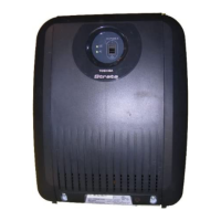
Figure 2-6 Mounting CTX100 Cabinet on Back Cover
10. Earth the system according to “AC Power and Earthing Requirements” on Page 2-4.
11. Go to “Step 8: Set Jumpers and Install Option PCBs onto the ACTU” on Page 2-17.
Step 5: Mount the Expansion Cabinet (if required)
1. Turn Base Cabinet DC power switch Off. Remove the four screws on the right side cover of the
Base Cabinet.
1. Remove four screws from the right side of the Base Cabinet (since they will interfere with
attaching the Expansion Cabinet to the Base Cabinet later).
2. Remove the Expansion Cabinet back cover from the Expansion Cabinet (see Figure 2-4).
3. Place the Expansion Cabinet back cover next to the Base Cabinet back cover, making sure
expansion back cover hooks fit into the base back cover flanges (see Figure 2-5).
4. Mark the location of the four screw holes – there is one on each corner.
Make sure the location of the Expansion Cabinet meets the minimum clearance requirements
specified in Figure 2-1 on Page 2-3.
5. Drill holes on these marks.
6. Place the Expansion Cabinet back cover on the wall back board and secure the back cover to the
back board with four screws.
7. On the right side of the AMAU motherboard inside the Base Cabinet, flip open the top and bottom
locks for data ribbon cable plug. Plug in the data ribbon and close the locks. Feed the ribbon
through the side hole of the Base Cabinet.
WARNING! To prevent electrical shock, make sure the power supply is not plugged into
the AC outlet.
Hanger
Back C over
Bottom left
hanger is only
used on the
Base C abinet
Hanger Hole
Mount Cabinet - S lide
left
Unmount C abinet - S lide
right and up
5937

 Loading...