Strata CTX Configuration
1-9
Strata CTX I&M September 2002
Expansion Cabinets
One to six Expansion Cabinets can be added to increase the system station and Exchange line capacity.
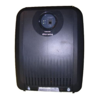
Each expansion cabinet provides 10 slots (S_01~S_10). Figure 1-4 shows an Expansion Cabinet.
Refer to the following section for cabinet slot and station/line capacities. Tables 1-5 and 1-6 show the
number of stations and Exchange lines allowed when additional cabinets and PCBs are used.
CTX670 Remote Expansion Cabinet
A CTX670 Expansion Cabinet can be located up to three kilometers from its Base Cabinet. Remote
Expansion Cabinets are enabled by the RRCU PCB. One RRCU connects to up to two ribbon-type
Data Cables and applies the inter-cabinet signal to a multi-mode fibre-optic pair. One fibre pair can
support one or two expansion cabinets in one remote location using one RRCU in the Base Cabinet
and another in the Remote Expansion Cabinet.
The CTX670 Base Cabinet supports up to six Remote Expansion Cabinets (at least one RRCU PCB is
required for each remote location).
Remote cabinets support the BIOU for external Page Zones, Night Bell, etc., and all Exchange line and
trunk interface PCBs. Network clock synchronisation can only be derived from digital trunks installed
in the Base Cabinet (Master) location.
S_01 S_02 S_03 S_04 S_05 S_06 S_07 S_08 S_09 S_10
5003
CABINET NO.
2
S_01 S_02 S_03 S_04 S_05
S_06 S_07 S_08 S_09 S_10
34567
POW
+5V
-5V
P. F.
RESET
EXP
BASE
AC IN
AC IN
DC OUT
-27V1
-27V2
-27V3
-27V4
+
-
POWER
ON
OFF
FG
5002
POW
+5V
-5V
P. F.
RESET
EXP
BASE
AC IN
BATT
DC OUT
-27V1
-27V2
-27V3
-27V4
+
-
POWER
ON
OFF
FG
5002
Figure 1-4 Strata CTX670 Expansion Cabinet Interior

 Loading...