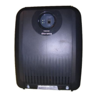
PCB Installation
4-3
Strata CTX I&M September 2002
ADKU – Digital Telephone Interface Unit
Circuits per PCB:
eight digital telephone circuits
Interfaces with:
all Toshiba digital telephones (DDCB, DSS, ADM, BPCI)
Older Version(s):
none
ADKU Hardware Options
The ADKU digital telephone interface unit only works with the CTX100. Refer to Chapter 7 – Station
Apparatus for instructions on how to connect digital telephones, DDCBs, and DDSS consoles to the
ADKU, as well as how to upgrade digital telephones with these options: a PC Interface Unit (BPCI), a
Speaker Off-hook Call Announce upgrade (BVSU), and a Headset/External Speaker (BHEU).
ADKU Installation
➤
Insert the ADKU (component side facing right) into the appropriate slot, and apply firm, even
pressure to ensure proper mating of connectors.
ASTU – Standard Telephone Interface Unit
Circuits per PCB:
two single line telephone circuits
Interfaces with:
Standard two-wire devices
Older Version(s):
none
ASTU Installation
Cabinet Slot
CTX100 has flexible 8 slots (Base:S101-S104 and Expansion:S105-S108). ASTU is configured with
reserved (fixed) slot of S109.
Table 4-1 ASTU PCB
Table 4-2 ASTU Electrical Characteristics
Standard Telephone Interface Unit (ASTU1)
Provides two standard telephone circuits. Interface with:
Standard telephones (No message
waiting)
Other single-line devices
Alternate BGM source
Fax machine
Voice mail devices
ASTU
Ring Voltage Square wave 190 250V peak-to-peak
(no-load)
Ringing Capacity 2 REN maximum per circuit

 Loading...