PCB Installation
4-4
Strata CTX I&M September 2002
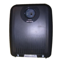
The figure below shows where to install the ASTU on the CTX100 Base cabinet. Table 4-3 shows the
interface connectors.
Figure 4-1 ASTU Installation
Note
Important safety information is detailed in the chapter ‘Notes to Users’ at the end of this
manual.
Table 4-3 ASTU Interface Connectors
Connector Type of Component Description
Connector cable P1 5 wire cable Connects to the motherboard for supply
power
Connector cable P2 10 wire cable Connects to the processor PCB for
data and signal highway
J1, J2 RJ11 Interface with single line devices
FG 1 Green wire Protection from hazardous voltage
ASTU position
Hole for FG wire (FG1). The earthing lead from the ASTU
must be terminated here.
4 Holes
Connecter from Base Cabinet
This connector of 5 cables is for power

 Loading...