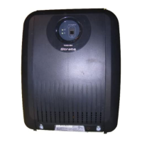
Strata CTX Configuration
1-18
Strata CTX I&M September 2002
Figure 1-6 CTX670 System Processor and Optional Interface PCBs
Data and S peec h Highway
5413
BEC U
P roc essor P C B
BBC U
P roc essor P C B
Interface P C B
R elay C ontac ts, P age Output
Music S ourc e: External Zone P age
Background Music
Door L oc k C ontrol R elay
External Zone P age R elays (4 Zones)
External P age A mplifier (600 ohm Output)
Main Distribution
F rame (MDF )
Night Bell Control Relay
Battery C harger
12V
Battery
12V
Battery
(2 or 4 Batteries)
MOH/BGM J ack
+Volume C ontrol
BP S U672
C abinet
Power Supply
MOH/BGM
Volume Controls
Up to Four Programmable S erial (RS-232)
P ort Modular J ac ks A vailable
ACD
(CS TA)
SMDR
C all Acc ounting
Amplified P age Output (3 W atts)
Remote CTX
WinAdmin P C
Local CTX
WinAdmin
BGM Mute Control R elay
Night Control Relay
Notes
1. Not required for one to two cabinets.
Required for three or more cabinets.
2. Optional. See description of License Control
earlier in this chapter.
3. Optional one or two per system.
25 P air
Music Source 1: Background Music
and/or Music -on-hold
Music Source 2: Background Music
and/or Music -on-hold
Music Source 3: Background Music
and/or Music -on-hold
2
BEXS
1
Expansion
Module
BBMS
1
Expansion
Memory
R emote Maintenanc e
Modem (Built-In)
BS IS
(Optional)
C onferenc e
SW with PAD
Ethernet
Interface
DTMF/ABR
R eceivers
( Built-In )
DTMF/ABR
R eceivers( Built-In )
BIOU
3
RJ45
Smart Media
Maintenanc e
and
C ustomer
Database
L icense
Internet
Attendant
C onsole (see
Fig. 8 for BATI
connec tion)
MOH/BGM
RCA Jacks
Hub
or
LAN
S MDI and S tratagy ES Integration
Toshiba P roprietary S oft K ey L C D L ink
Stratagy ES
Voic e Mail
On this page, all equipment, except Stratagy ES,
connected to the system processor PCBs and
BIOU PCB is customer-supplied.
For VM port connection,
see Figure 1-8.

 Loading...