2. Installation and Wiring
10
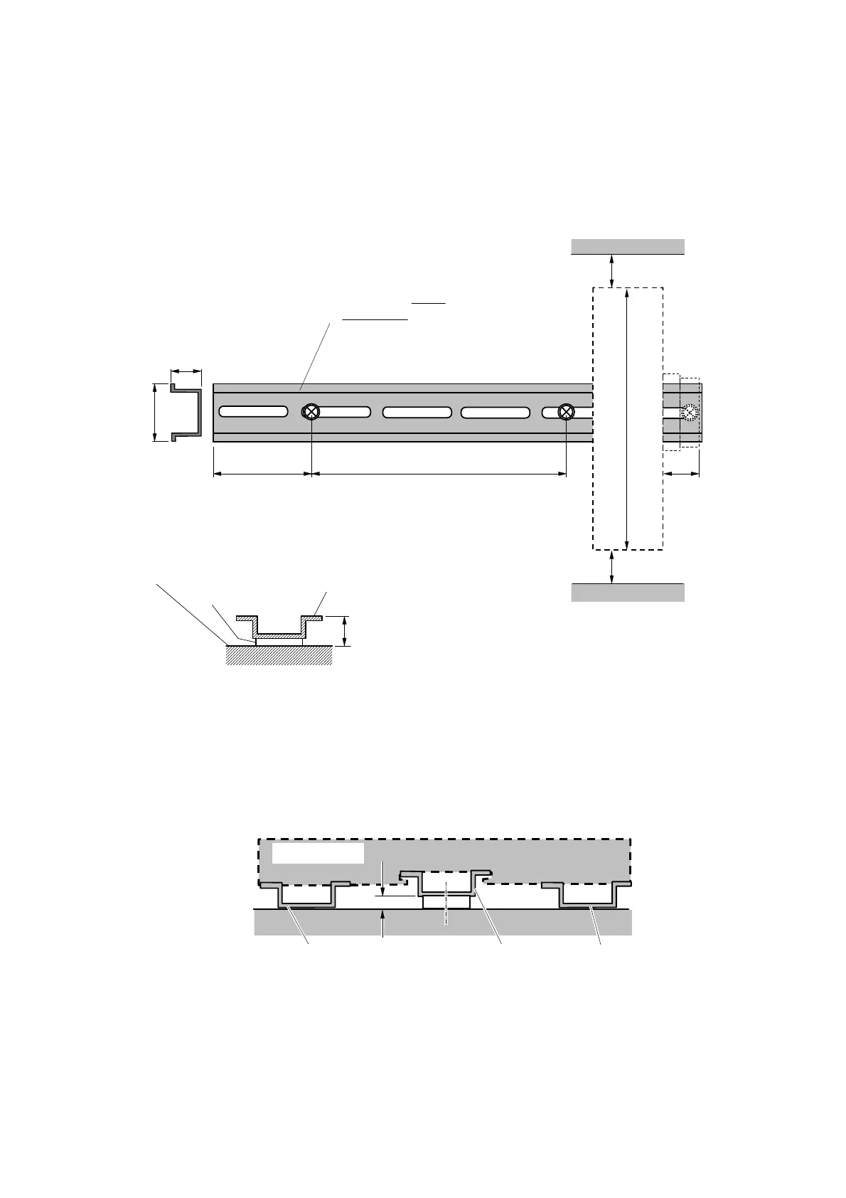
When mounting the DIN rail of the I/O base unit, make sure to meet the following conditions
in view of base unit mounting/demounting and strength.
g( >35mm)
s( >18mm)
15 m m
35mm
c( <50mm)
p( <250mm)
g( >35mm)
ベースユニッ ト 高さ 160mm
DIN レ ールは取付面高さ 15mm、 鉄製のも のを推奨致し ま す。
s(>18mm)
g(>35mm)
In the case DIN rails in general (height: 7.5 mm),
it is difficult to install thebase unit.
Insert a spacer whose height from the DIN rail
mounting face is at least 10mm.
Note 2:
Spacer
DIN rail mounting face
Mounting DIN rail
h(>10mm)
Base unit height 160 mm
g(>35mm)
Recommended DIN rails are 15 mm in their mounting
face height and madeof steel.
When fixing a DIN rail, the spacing between screws (p) should be within 250 mm
andthe spacing between both sides of the screw and the fixing screw (c) should be
within 50 mm. The top-to-bottom spacing (c) of the base unit should be at least 35
mm. Leave at least 18 mm of rail left to right as the stopper space (s).
c(<50mm) p(<250mm)
15mm
35mm
Note 1:
Figure 2.2 I/O Base Unit Mounting Method
Vibration Measure
In the event that measures against vibrations on top and bottom of the base unit are necessary
when the vibrations of the mounting face are large, it is desirable to add/insert reinforcing
supports (such as DIN rails) as shown in Figure 2.3.
ベースユニッ ト
補強挿入 DIN レ ール
取付 DIN レ ール
4mm スペーサー
補強挿入 DIN レ ール
Base unit
Reinforcing insertion DIN rail
4-mm spacer
Mounting DIN rail
Reinforcing insertion DIN rail
Figure 2.3 Anti-vibration Measure
 Loading...


