3. DISASSEMBLY AND REASSEMBLY
SPAA-214-R1
3.2 DISASSEMBLING THE MAIN BODY
3-11
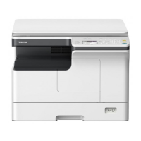
4. Remove the 2 screws to release the PCB Stay from the Print Block.
The PCB Stay may now be removed from the Print Block in the direction indicated by the
arrow.
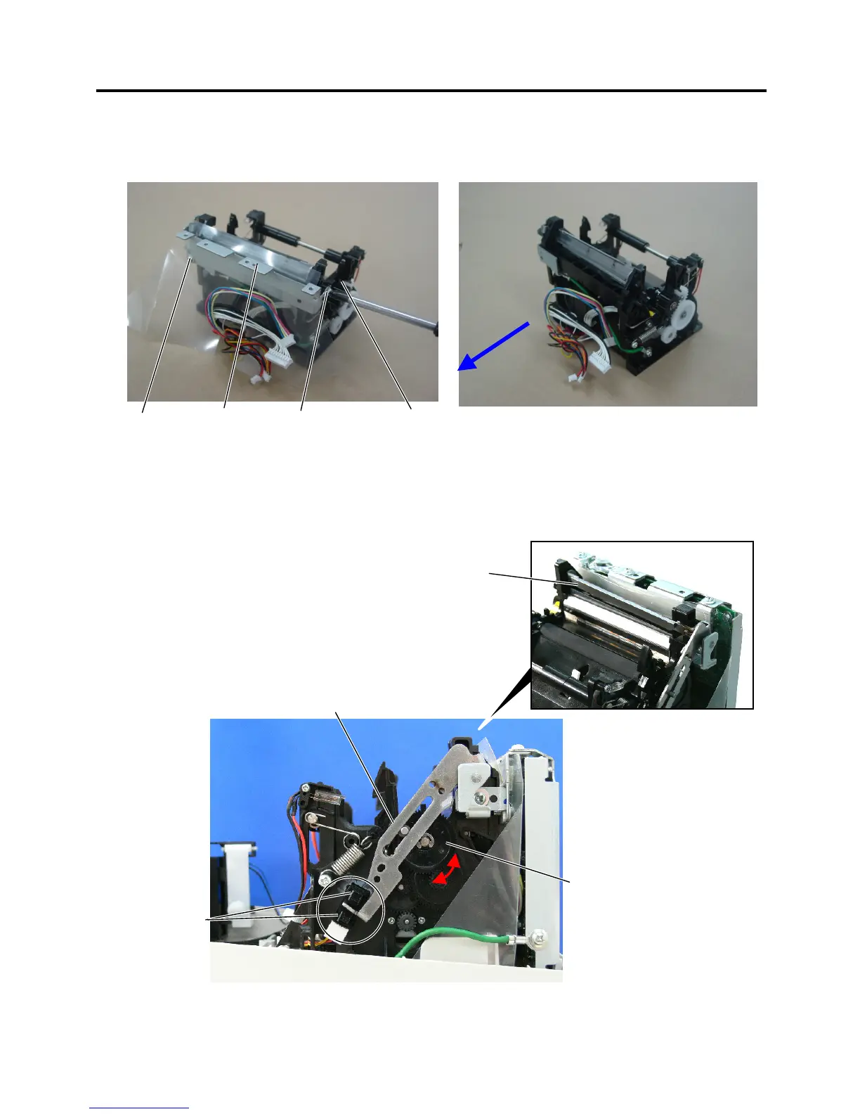
NOTE: Please note the following when reassembling the Print Block.
After attaching the Print Block to the Cover Bottom, make sure the Cutter Arm is at the
position where it blocks the Cutter Home Position Sensor. Otherwise, the Cover may
not be firmly closed and the Upper Platen may damage the Cutter Blade. If the Cutter
Arm is not at the position as shown in the photo, rotate the Cutter Gear to adjust the
Cutter Arm position.
3x6 p-tite
Print Block
PCB Stay
3x6 p-tite
Cutter Arm
Cutter Home
Position Sensor
Cutter Gea
 Loading...