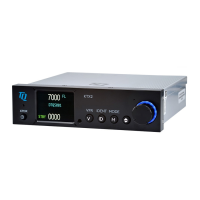
TQ Aviation KTX2-F.0100
EASA.AP445 MAN
KTX2-F.A-MAN.0001.docx Page 61 of 74
© TQ-Systems GmbH. All information contained in this documents have to be treated strictly confidential. The transfer of presentations and know-how to third parties
requires the prior written consent of TQ-Systems GmbH.
• Standard 50 Ω, vertically polarized antenna with a VSWR < 1.7:1 at 1090 MHz.
• TSO-C66( ), TSO-C74( ), TSO-C112( ) , or TSO-154c antennas that also meet the VSWR
specification.
Only the L-Band antennas listed in the table below have been tested for compatibility with transponder
installations.
Type
RAMI
-74 BNC
Comant CI-105 BNC
Comant CI-105-11 TNC
Table 8: L-Band Antennas
5.1.6.2 Antenna Installation
The antenna should be installed according to the manufacturer’s instructions.
The following considerations should be taken into account for the antenna installation:
• The antenna should be placed not directly near any projections, the engine(s) and propeller(s). It
should also be placed not directly near landing gear doors, access doors or others openings
which will break the ground plane for the antenna.
• The antenna should be mounted on the bottom surface of the aircraft and in a vertical position
when the aircraft is in level flight.
• The antenna should not be mounted within 3 feet of the ADF sense antenna or any COMM
antenna and 6 feet from the transponder to the DME antenna.
• Where practical, the antenna location should be chosen to keep the cable lengths as short as
possible and to avoid sharp bends in the cable to minimize the VSWR.
• To prevent RF interference, the antenna must be physically mounted at a minimum distance of 3
feet from the transponder.
Electrical connection to the antenna should be dust and water proof to avoid loss of efficiency as a result
of the presence of liquids or moisture. All antenna feeders must be installed in such a way that a
minimum of RF energy is radiated inside the aircraft.
5.1.6.3 Antenna Cable
The transponder is designed to fulfil the ADS-B Class 1 requirements allowing a maximum loss of 2 dB
in the connectors and cable used to connect it to the antenna. Exceeding this loss will degrade the
transmitter output power and receiver sensitivity.
A typical installation needs two (2) connectors at each end of the antenna cable.
Calculating a loss of 0.25dB for each connector allows a loss of 1.5dB for the cable itself.
An acceptable cable must have the following characteristics:
• Less than 1.5dB loss for the cable length needed.
• Characteristic impedance of 50 Ohms.

 Loading...