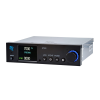
TQ Aviation KTX2-F.0100
EASA.AP445 MAN
KTX2-F.A-MAN.0001.docx Page 7 of 74
© TQ-Systems GmbH. All information contained in this documents have to be treated strictly confidential. The transfer of presentations and know-how to third parties
requires the prior written consent of TQ-Systems GmbH.
5.1.4 Static Air Port ............................................................................................................... 60
5.1.5 GNSS Interface ........................................................................................................... 60
5.1.6 Antenna Connector ...................................................................................................... 60
5.2 Wiring .............................................................................................................................. 64
5.2.1 Conductor Cross Section ............................................................................................. 64
5.2.2 Wiring Scheme ............................................................................................................ 64
6. Drawings ................................................................................................................................. 65
7. Technical Data ........................................................................................................................ 67
7.1 General ........................................................................................................................... 67
7.2 Transmitter – Receiver .................................................................................................... 69
8. FCC related issues .................................................................................................................. 70
8.1 Radiofrequency radiation exposure Information: .............................................................. 70
8.2 Compliance ..................................................................................................................... 70
8.3 Modifications ................................................................................................................... 70
9. Maintenance ........................................................................................................................... 71
9.1 Periodic Maintenance ...................................................................................................... 71
9.2 Repair .............................................................................................................................. 71
9.3 Cleaning .......................................................................................................................... 71
10. EXCLUSIVE LIMITED WARRANTY and LIMITATIONS ON LIABILITY ............................... 72
11. Software License Conformity ............................................................................................... 73
List of Tables
Table 1: Transponder Modes ................................................................................................................. 22
Table 2: GND Switch Support ................................................................................................................ 40
Table 3: Certitified GNSS Units .............................................................................................................. 42
Table 4: Approved GNSS Units .............................................................................................................. 42
Table 5: List of supported GNSS Devices .............................................................................................. 43
Table 6: Degrading Failures ................................................................................................................... 54
Table 7: Severe Failures ........................................................................................................................ 57
Table 8: L-Band Antennas ..................................................................................................................... 61
Table 9: Common Antenna Cables ........................................................................................................ 62
Table 10: Technical Data ....................................................................................................................... 68
Table 11: Transmitter Data .................................................................................................................... 69
Table 12: Receiver Data ........................................................................................................................ 69
Table 13: General Data .......................................................................................................................... 69
List of Figures
Figure 1: Display Diagram ...................................................................................................................... 17
Figure 2: Controls .................................................................................................................................. 18
Figure 3: Indicators ................................................................................................................................ 19
Figure 4: Operational menu structure ..................................................................................................... 20
Figure 5: Initial Display ........................................................................................................................... 21
Figure 6: Normal Operation .................................................................................................................... 22
Figure 7: VFR-Squawk ........................................................................................................................... 24
Figure 8: Squawk Ident .......................................................................................................................... 25
Figure 9: Airborne/Ground Indication "FLY" ........................................................................................... 26
Figure 10: Airborne/Ground Indication "GND" ........................................................................................ 26
Figure 11: ADS-B Indication ................................................................................................................... 27
Figure 12: Change Flight ID ................................................................................................................... 28
Figure 13: Change Brightness................................................................................................................ 28
Figure 14: GNSS Data Display ............................................................................................................... 30
Figure 15: Button functions in Setup Mode............................................................................................. 31

 Loading...