TR-Electronic GmbH 2017, All Rights Reserved Printed in the Federal Republic of Germany
Page 38 of 52 TR-ELA-BA-DGB-0026-04 01/26/2023
4.2 IO-Link
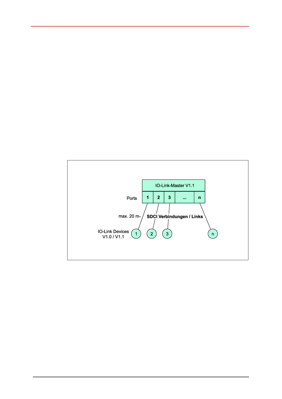
A point-to-point connection is set up between an IO-Link master and the measuring
system using an unshielded three-core cable.
Make sure that the maximum cable length between the IO-Link master and an IO-Link
device (per device) does not exceed 20 m. A cable with a minimum core cross-
sectional area of 0.35 mm
2
is recommended.
The measuring system is connected about an A-coded four-pole connector.
By the three wires of the control line two wires are used for the supply voltage and one
wire for the IO-Link communication connectivity. The 0 V – supply line is also
reference potential of the IO-Link communication connectivity.
With this connection type the measuring system is compatible in accordance with the
IO-Link specification “Port Class A”. Here, the maximum current consumption of these
devices is specified to ≤ 200 mA.
A data transmission rate of 230.4 kbit/s is supported by the measuring system, this
corresponds to the SDCI communication mode “COM3”.
Figure 2: SDCI topology
Over the cyclic data exchange the measuring system uses 6 bytes input data and
0 bytes output data.
Structure of the process data:
- IN: 4 bytes position data
- IN: 2 bytes velocity data
- OUT: 0 bytes



 To Next Page