TR-Electronic GmbH 2017, All Rights Reserved Printed in the Federal Republic of Germany
Page 40 of 52 TR-ELA-BA-DGB-0026-04 01/26/2023
6 Commissioning
6.1 IO-Link device description file (IODD)
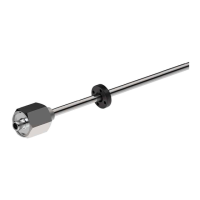
With the measuring system also an electronic device description is provided, the so-
called "IODD file" (IO Device Description). The IODD file is used for the IO-Link
system integration and commissioning of the measuring system.
The IODD file is XML-based and can be read-in by each IO-Link Configuration Tool.
Download:
• LMP-30 – Measuring range ≤ 1m (TR-Linear_020012):
www.tr-electronic.de/f/TR-ELA-ID-MUL-0026
• LMP-30 - Measuring range > 1m (TR-Linear_020022):
www.tr-electronic.de/f/TR-ELA-ID-MUL-0031
• LM_S-34 - Measuring range ≤ 1m (TR-Linear_020030):
www.tr-electronic.de/f/TR-ELA-ID-MUL-0030
• LM_S-34 - Measuring range > 1m (TR-Linear_020040):
www.tr-electronic.de/f/TR-ELA-ID-MUL-0032
6.2 Device identification
Each IO-Link device possesses a device identification. It consists of a firm
identification, the VendorID, and a manufacturer-specific part, the DeviceID. The
VendorID is assigned by the PNO. For TR-Electronic the VendorID contains the
value 0x0153, the DeviceID is device specific.
When the system boots up the projected device identification is examined. In this way
errors in the project engineering can be recognized.
6.3 Starting up on the IO-Link – system
If the measuring system is connected to an IO-Link master and the operation mode is
set to IO-Link, the IO-Link master attempts to communicate with the connected
measuring system. To do so, the IO-Link master sends a Wake-Up Request and
waits for the measuring system to reply.
If the IO-Link master receives the reply from the measuring system and the
transmission rate COM 3 = 230.4 kbaud was adjusted by the IO-Link master, the
communication begins. Next, communication parameters are exchanged and if
necessary, parameters saved in the system will be transmitted to the measuring
system. Then, the cyclic exchange of the process data and value status begins.
 Loading...