Installation
30 RT-SVX21AC-EN
3. Rig the unit as shown in the weights section. Attach
adequate strength lifting slings to all four lifting
brackets in the unit base rail. Do not use cables, chains,
or slings except as shown.
4. Install a lifting bar, as shown in the
weights section to
protect the
unit and to facilitate a uniform lift. The
minimum distance between the lifting hook and the
top of the unit should be 7 feet.
5. Test-lift the unit to ensure it is properly rigged and
balanced, make any
necessary riggin
g adjustments.
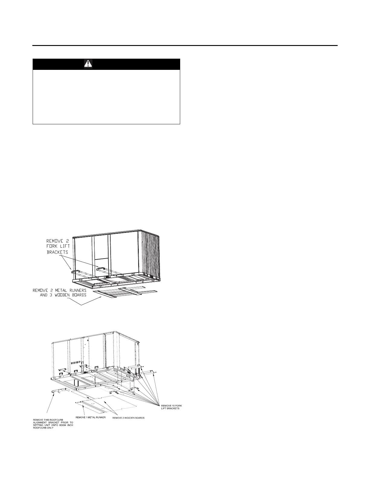
6. Lift the unit enough to allow the removal of base fork
pocket protection components as shown in the
following figures.
7. When 10 ton high efficiency units are
installed on
smaller
existing roof curb (50"x 84") for replacement
applications, do not remove alignment bracket. This
bracket helps assure proper alignment of duct
openings.
8. Downflow units; align the base rail of the
unit with the
curb rail while lowering the unit onto the curb. Make
sure that the gasket on the curb is not damaged while
positioning the unit.
General Unit Requirements
The checklist listed below is a summary of the steps
required to successfully install a commercial unit. This
checklist is intended to acquaint the installing personnel
with what is required in the installation process. It does not
replace the detailed instructions called out in the
applicable sections of this manual.
• Check the unit for shipping damage and material
sh
ortage; fil
e a freight claim and notify appropriate
sales representative.
• Verify correct model, options and voltage from unit
n
ameplate.
•
Verify that the installation location
of the unit will
provide the required clearance for proper operation.
• Assemble and install the roof curb (if applicable).
Refer
to the latest edition of the curb in
stallers guide that
ships with each curb kit.
• Fabricate and install ductwork; secure ductwork to
curb.
• Install pitch pocket for power supply through building
roof. (If applicable)
• Rigging the unit.
• Set the unit onto the curb; c
heck for levelness.
• Ensu
re unit-to-curb seal is tight and without buckles or
cracks.
• Install
and connect a condensate drain line to the
evaporator drain con
nection.
Note: Co
ndensate Overflow Switch (if equipped) will not
wo
rk if unit is not leveled properly.
Factory Installed Economizer
• Ensure the economizer has been pulled out into the
operating position. Refer to the economizer
installation guide for proper position and setup.
• Install all access panels.
WARNING
Improper Unit Lift!
Failure to properly lift unit could result in unit dropping
and possibly crushing operator/technician which could
result in death or serious injury, and equipment or
property-only damage. Test lift unit approximately 24
inches to verify proper center of gravity lift point. To
avoid dropping of unit, reposition lifting point if unit is
not level.
Figure 40. Fork pockets - all units except 10 ton high
effic
iency units
Figure 41. Fork pockets - 10 ton high efficiency unit