Sequence of Operation
64 RT-SVX21AC-EN
voltage. Adjust potentiometer until output voltage
across TP1 and ground achieves desired CFM setpoint.
2. To increase voltage/CFM, turn potentiometer
clockw
ise.
3. To d
ecrease voltage/CFM, turn potentiometer counter-
clockwise.
Note: With ID fan access panel removed, fan will operate
at lower RPM due to the decrease in pressure. Once
panel is installed, RPM will increase.
17 Plus units with the constant CFM direct
drive indoor fan
Proper airflow is critical to unit operation. All 17 Plus
Precedent units (037, 047, and 067 units) use an indoor fan
that provides a constant CFM. There are two different
types of 17 Plus Precedent units: Single Zone VAV units
and Multi Speed units. Both types of units use the same
type of indoor motor and the same airflow adjustment
procedure.
To adjust airflow on a 17 Plus unit the Service Test mode
must
be used for accurate results. Additionally, airflow
adjustments should be made in either “Cool Stage 2" or
any stage of heat because the fan is driven to its maximum
setting during these stages. Only the maximum fan setting
requires adjustment, all other fan speeds follow the
maximum adjustment and do not require any adjustment.
Using the Service Test Guide in Table 16, p. 51, enter the
un
it into either “Cool Stage 2" or any stage of heat by using
either the “Step Test Mode” or “Resistance Test Mode”.
Once the unit is in either “Cool Stage 2" or any stage of
heat, system ai
rflow (CFM) is determined by:
1. In the indoor fan compartment, locate the R136
potent
iometer on the RTOM
circuit board (also
designated “DA COOL - FAN SPD”). Also, locate the
TP1 test pin loop next to the R136 potentiometer.
2. Measure the DC Voltage across the test pin TP1 and
un
it chassis g
round. Compare DC voltage to the CFM
chart shown in Table 23, p. 64. Table 23, p. 64 shows
what DC voltage corresponds to CFM per ton of unit
cooling.
Note: If
1200 cfm is required from a 3 ton unit
(037) the R136 potentiometer should be
a
djusted so that the DC voltage measured
at TP1 to ground reads 1.65 volts DC.
3. To increase the TP1 voltage, turn the R136
potent
iometer clockwise.
4. To
decrease the TP1 voltage, turn the R136
potentiometer counter-clockwise.
Note: Wi
th the
indoor fan access panel remo
ved, the fan
will operate at a lower RPM because static pressure
is reduced with the door open. Once the panel is
returned the RPM of the indoor fan will increase.
Variable Air Volume Applications
(Traditional VAV)
Supply Air Temperature Control - Occupied
Cooling and Heating
The RTRM is designed to maintain a selectable supply air
temperature of 40°F to 90°F with a +/- 3.5°F deadband. In
cooling, if supply air temperature is more than 3.5 degrees
warmer than the selected temperature, a stage of cooling
will be turned “On” (if available). Then if the supply air
temperature is more than 3.5° cooler than the selected
temperature, a stage of cooling will be turned “Off”. At
very low airflows the unit may cycle stages “On” and “Off”
to maintain an average discharge air temperature outside
the 7° deadband. During low load or low airflow conditions
the actual temperature swing of the discharge air will likely
be greater. The RTRM utilizes a proportional and integral
control scheme with the integration occurring when the
supply air temperature is outside the deadband. As long as
the supply air temperature is within the setpoint
deadband, the system is considered to be satisfied and no
staging up or down will occur.
Note: Th
e RTRM is designed to maintain a selectable
supply ai
r temperature of 40°F to 90°F with a +/-
3.5°F deadband. However, to reduce the risk of
evaporator coil freeze-up in Precedent and Voyager
Light Commercial applications, supply air
temperature should not be set below 50° F.
Supply Air Temperature Control with an
Economizer
The economizer is utilized to control the supply air cooling
at +1.5°F around the supply air temperature setpoint range
of 40°F and 90°F providing the outside air conditions are
suitable. To reduce the risk of evaporator coil freeze-up
supply air temperature should not be set below 50° F.
While economizing, the mechanical cooling is disabled
until the economizer dampers have been fully open for
three minutes. If the economizer is disabled due to
unsuitable conditions, the mechanical cooling will cycle as
though the unit had no economizer.
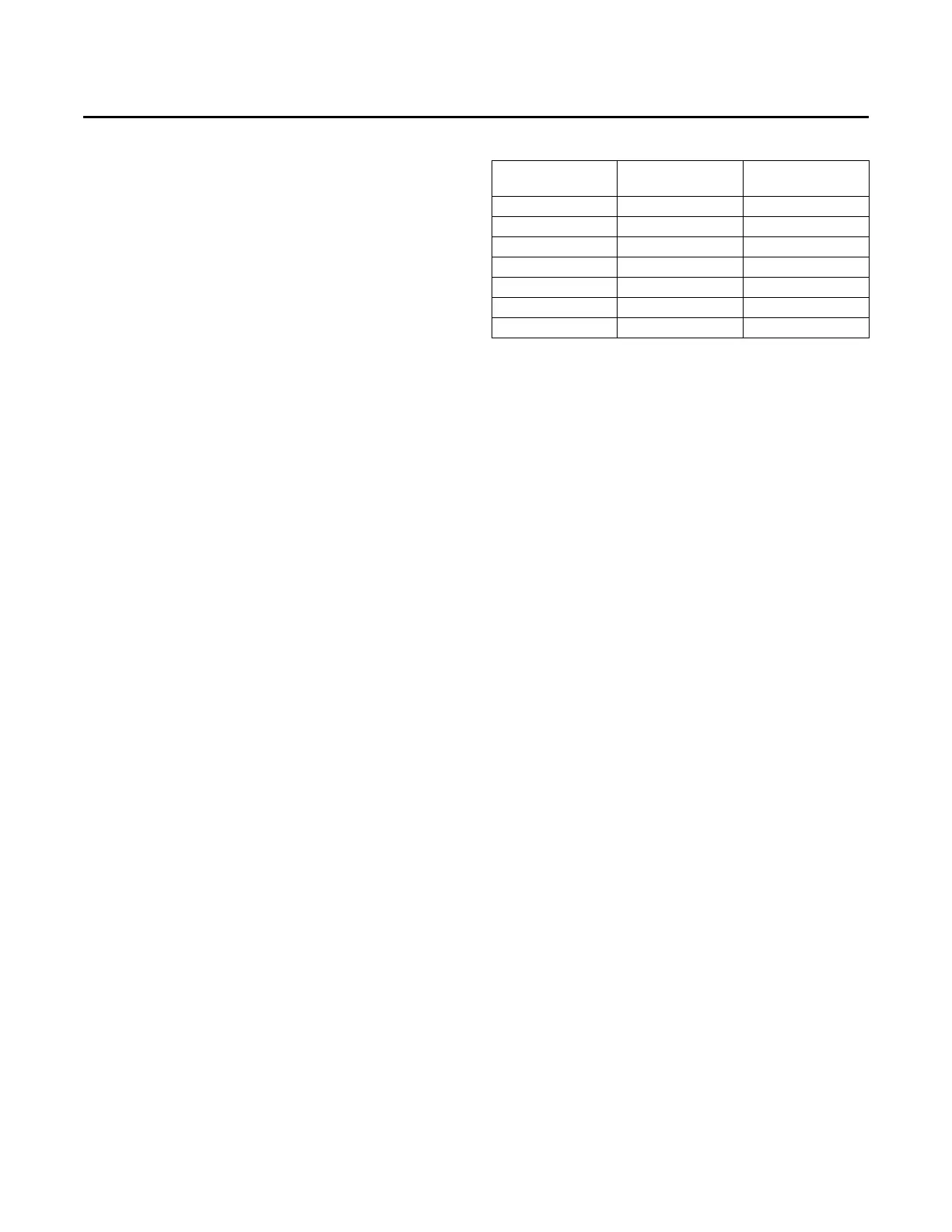
Table 23. Cfm vs. vdc
PWM% value
Potentiometer
Voltage (Vdc) CFM/Ton
70 <0.1 320
75 0.7 347
80 1.25 373
85 1.65 400
90 1.95 427
95 2.17 453
100 >2.4 480