Sequence of Operation
RT-SVX21AC-EN 61
Drain Pan Condensate Overflow Switch
(Optional)
The condensate overflow switch (COF) is utilized to
prevent water overflow from the drain pan. The float
switch is installed on the corner lip of the drain pan. When
the condensate level reaches the trip point, the COF relay
energizes and opens the 24 Vac control circuit which
disables the unit. Once the 24 Vac control circuit is opened,
a delay timer will prevent unit start-up for three minutes.
Verifying Proper Air Flow
Units with 5-Tap Direct Drive Indoor Fan
Much of the systems performance and reliability is closely
associated with, and dependent upon having the proper
airflow supplied both to the space that is being
conditioned and across the evaporator coil.
The indoor fan motor is factory wired to operate on speed
tap
1 in the coo
ling and heating mode for electric/electric
units. For Gas/Electric units, the motor is factory wired to
operate on speed tap 1 during cooling. For 3 and 4 ton Gas/
Electric units operating in heat mode, the minimum
setting is Tap 4.
For these units, a separate tap terminal is provided to
chan
ge speeds automatically between heating and
cooling. The motor can be rewired for different speed
settings should the application require it. Refer to the
wiring diagram that shipped in the unit and the unit fan
performance tables in the Service Facts.
The indoor fan motors are specifically designed to operate
within the
BHP parameters listed in the fan performance
tables of the unit Service Facts.
When verifying direct drive fan performance, the tables
mu
st be used so
mewhat differently than those of belt
driven fans. Fan performance diagnostics can be easily
recognized when these tables are used correctly.
Before starting the SERVICE T
EST, set the mi
nimum
position setpoint for the economizer to 0 percent using the
setpoint potentiometer located on the Economizer Control
(ECA), if applicable.
ReliaTel™ Control: Using the Service Test Guide in
Table 16, p. 51, momentarily jump across the Test 1 and
Test 2 terminals on LTB1 one time to start the Minimum
Ventilation Test.
Electromechanical Control: Using the Service Test
Guide perform the proper test mode connections.
With the fan operatin
g prop
erly, determine the total
system external static pressure (inches w.c.) by the
following method (ReliaTel™/Electromechanical):
1. Measure the supply and return duct static pressure and
sum the resulting absolute
values,
2. Use the accessory pressure d
rop table
in the Service
Facts, to calculate the total static pressure drop for all
of the accessories installed on the unit; i.e., curb,
economizer, etc.
Note: Acces
sory static pressure drop
is based on desired
CFM and may not be actual static pressure drop.
3. Add the total accessory static pressure drop (step 2) to
the duct extern
al static pressure (step 1). The sum of
these two values represents the total system external
static pressure.
Using the Fan Performance Tables in
the Service
Facts,
look up the selected speed tap setting and match the
measured ESP to determine the approximate CFM.
If the required CFM is too low,
(external static pressure is
hi
gh) do one or both of the following and repeat
procedure:
a. Relieve supply and/or return duct static.
b. Change indoor fan speed tap to a higher value
If the required CFM is too high, (external static p
ressure is
low), do one or both of the following and repeat
procedure:
a. Increase supply and/or
return duct static.
b. Cha
nge indoor fan speed tap to a lower value.
Note: Minimum s
etting for units with
Gas or Electric Heat
is 320 CFM per Ton. For 3 and 4 Ton Gas Heat units
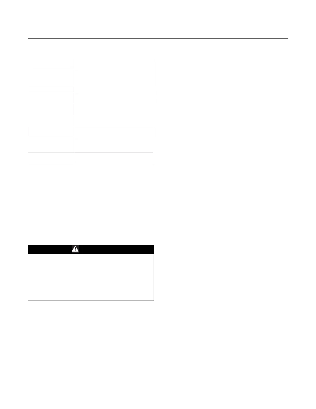
Table 21. Ignition module diagnostics
Steady light
Module is powered up, but no active call for
heat.
Blinking at
continuous steady
rate
Active call for heat.
One blink
Loss of communication.
Two blinks
System lockout (failure to ignite, no spark,
low/no gas pressure, etc.)
Three blinks
Pressure switch (no vent air flow, bad CBM,
closed at initial call for heat). Auto reset.
Four blinks
High limit (excessive heat in combustion
chamber, low airflow). Auto reset.
Five blinks
Flame sensed and gas valve not energized
or flame sensed and no call for heat.
Six blinks
Flame rollout (CBM failure, incorrect gas
pressure, incorrect primary air). Requires
manual reset of the switch.
Seven blinks
W1 and W2 swapped (electromechanical 3-
10 tons units).
WARNING
Live Electrical Components!
Failure to follow all electrical safety precautions when
exposed to live electrical components could result in
death or serious injury. When necessary to work with
live electrical components, have a qualified licensed
electrician or other individual who has been properly
trained in handling live electrical components perform
these tasks.