Installation
RT-SVX21AC-EN 33
5. Slide RETURN DUCT COVER (insulation side up) into
supply opening until inward edge of duct cover
engages with the 2 retaining clips on the duct flange.
Secure outward edge of the duct cover with two
screws.
6. After completing installation
of the duct covers for
horizontal discharge, proceed to TCO1 instructions.
TCO1 Instructions
If the unit being installed has a different TCO1 value (refer
to previous tables), the limit control TCO1 must be
replaced with the extra limit control shipped in the heater
compartment. Replace TCO1 following the instructions in
steps 1 through 3 below. If the unit being installed does not
correspond to any in the following list, skip steps 1 through
3 and go on to next step in the installation process.
1. Remove the heat section access panel.
2. Remove TCO1 from shipping location, attached to the
co
mbustion blower.
3. Replace and discard the existing TCO1 originally
in
stalled at the factory fo
r down flow operation with
the TCO1 shipped attached to the combustion blower
for horizontal operation.
4. Replace heat section access panel.
Horizontal Discharge Conversion
(6 to 10 Ton Units)
Note: 6 to 10 ton units the supply cover to return opening
and return cover to supply opening.
Supplies Needed by Installer for Conversion: 3 oz. tube of
h
igh T
emperature RTV sealant (500°F / 260°C: Similar to
Dow Corning 736).
Important: F
ailure to
use recommended sealant could
result in unit performance loss.
If a unit is to be converted to a Horizontal discharge, the
following conv
ersion must be performed:
1. Remove RETURN and SUPPLY duct covers.
2. Place SUPPLY DUCT COVER
over dow
n-flow return
opening. (insulation side down)
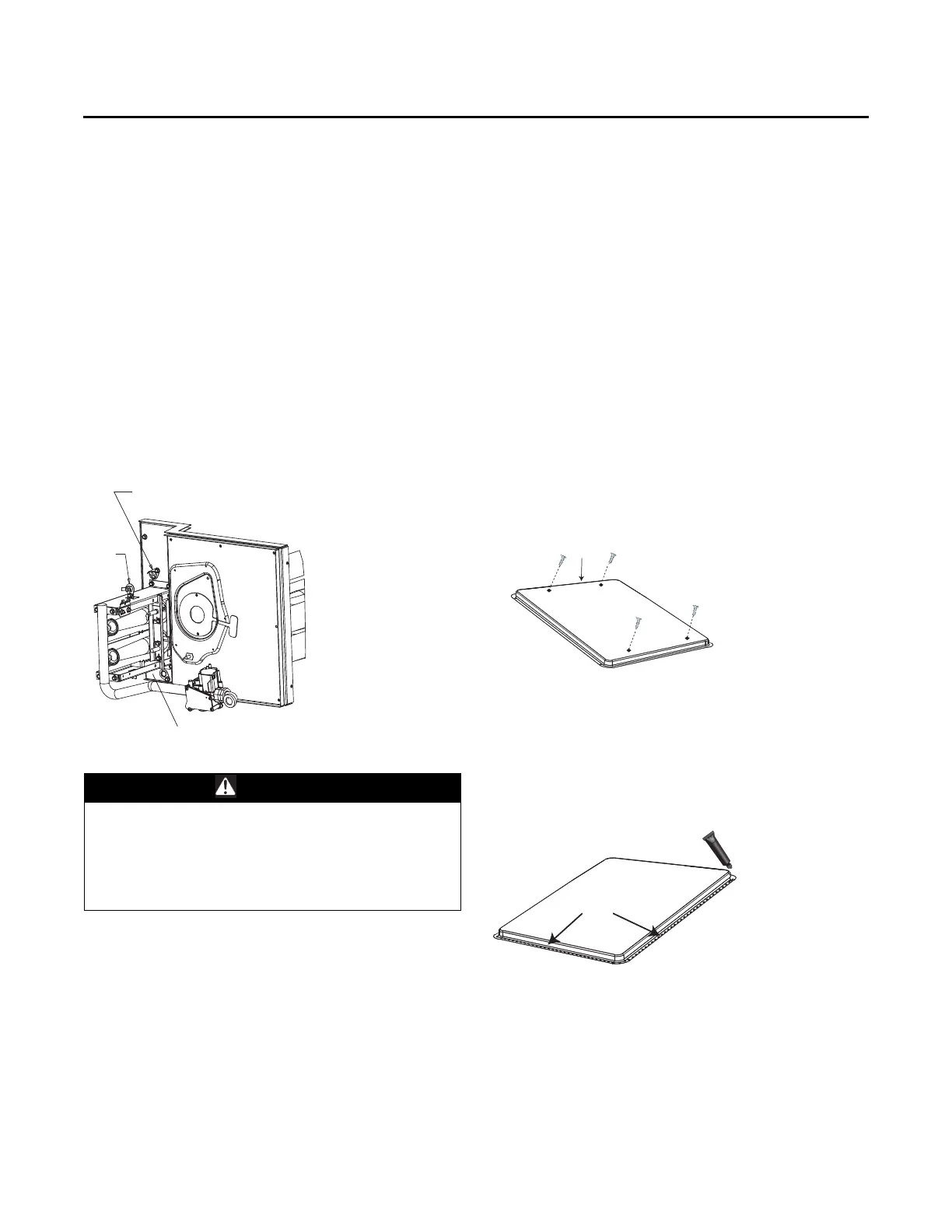
3. Using self-drilling screws, (or
screws removed from
duct cover), screw th
rough dimples to attach DUCT
COVER to base.
4. On original RETURN DUCT COVER, apply ¼”(6mm.)
continuous bead of 500°F RTV sealant around flange
(opposite insulation side), as shown.
5. Slide RETURN DUCT COVER (insulat
ion side up) into
supply opening until inward edge of duct cover
engages with the 2 retaining clips on the duct flange.
Secure outward edge of the duct cover with two
screws.
Notes:
• If
unit is equipped with Return Air Smoke Detector,
refer to field conversion instructions for horizontal
discharge b
efore installing return air duct.
Figure 44. TCO1 location (YHC036E, YHC037E)
WARNING
Hazardous Voltage!
Failure to disconnect power before servicing could
result in death or serious injury. Disconnect all electric
power, including remote disconnects before servicing.
Follow proper lockout/tagout procedures to ensure the
power can not be inadvertently energized.
Location of TC01 limit for
YHC036E and YHC037E units
Location of TC01 limit
YSC033-063G
Flame
Rollout
Limit
Figure 45. Duct cover
Figure 46. Duct cover
Supply Duct Cover
Screw into 4
dimples on top
edge
RTV Sealant