RT-SVX21AC-EN 69
Maintenance
Fan Belt Adjustment - Belt Drive
Units
The fan belts must be inspected periodically to assure
proper unit operation.
Replacement is necessary if the belts appear frayed or
worn. Units with dual
belts require
a matched set of belts
to ensure equal belt length.
When removing or installing the new belts, do not stretch
them over the she
aves. Loosen the belts using the belt
tension adjustment bolts on the motor mounting base.
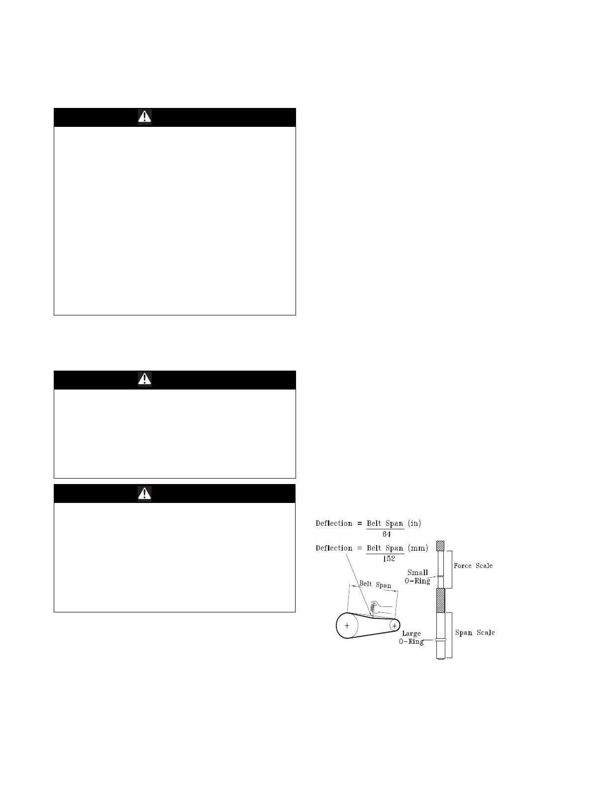
Once the new belts are installed, using a Browning or
Gates tension gaug
e (or equivalent) illustrated in
Figure 75, p. 69, adjust the belt tension as follows;
1. To determine the appropriate belt deflection;
a. Measure the center-to-center shaft distance (in
inch
es) between
the fan and motor sheaves.
b. Divide the distance measured in Step 1
a by 64; the
resulting value represents the amount of belt
deflection that corresponds to the proper belt
tension.
2. Set the large O-ring on the belt tension gauge at the
d
eflection va
lue determined in Step 1b.
3. Set the small O-ring at zero on the force scale of the
ga
uge plun
ger.
4. Place the large end of the gauge at the center of the belt
span, then d
epress the gauge plunger until the large O-
ring is even with the top of the next belt or even with
a straightedge placed across the fan and motor
sheaves. Refer to Figure 75, p. 69.
5. Remove the belt tension gauge. The small O-ring now
in
dicates a number other than zero on the plunger’s
force scale. This number represents the force (in
pounds) required to give the needed deflection.
6. Compare the “force” scale reading (Step 5) with the
a
ppropriate “fo
rce” value listed in Table 24, p. 70. If
the “force” reading is outside the range, readjust the
belt tension.
Note: Actu
al belt deflectio
n “force” must not exceed the
maximum “force” value shown in Figure 75, p. 69.
7. Recheck the belt tension at least twice during the first
2 to 3
days of operation. Belt tension may decrease
until the new belts are “run in”.
WARNING
Hazardous Service Procedures!
Failure to follow all precautions in this manual and on
the tags, stickers, and labels could result in death or
serious injury.
Technicians, in order to protect themselves from
potential electrical,
mechanical, and chemical hazards,
MUST follow precautions in this manual and on the
tags, stickers, and labels, as well as the following
instructions: Unless specified otherwise, disconnect all
electrical power including remote disconnect and
discharge all energy storing devices such as capacitors
before servicing. Follow proper lockout/tagout
procedures to ensure the power can not be
inadvertently energized. When necessary to work with
live electrical components, have a qualified licensed
electrician or other individual who has been trained in
handling live electrical components perform these
tasks.
WARNING
Live Electrical Components!
Failure to follow all electrical safety precautions when
exposed to live electrical components could result in
death or serious injury. When necessary to work with
live electrical components, have a qualified licensed
electrician or other individual who has been properly
trained in handling live electrical components perform
these tasks.
WARNING
Rotating Components!
Failure to follow all safety precautions below could
result in rotating components cutting and slashing
technician which could result in death or serious injury.
During installation, testing, servicing and
troubleshooting of this product it may be necessary to
work with live and exposed rotating components. Have
a qualified or licensed service individual who has been
properly trained in handling exposed rotating
components, perform these tasks.
Figure 75. Belt tension gauge
 Loading...


