Installation
34 RT-SVX21AC-EN
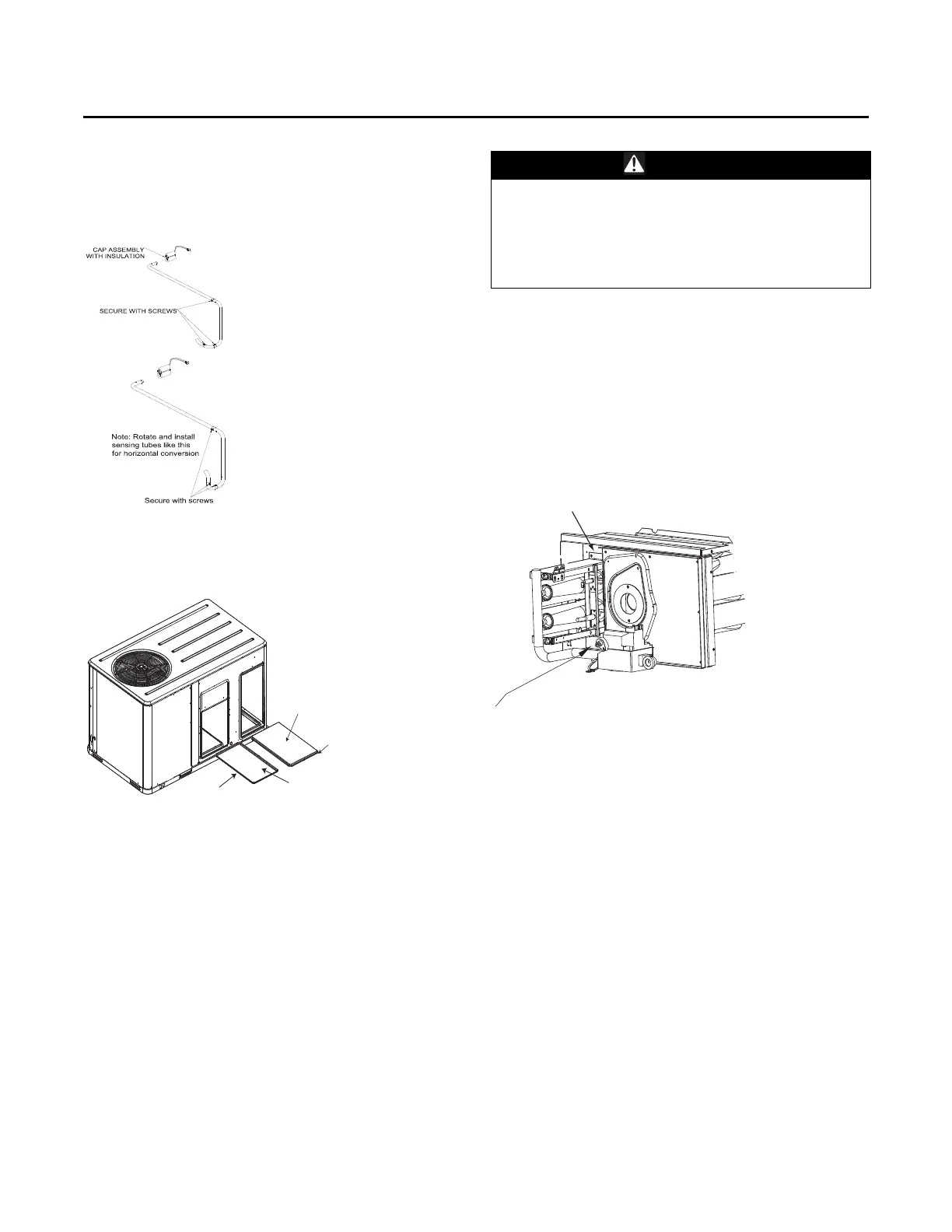
• If unit is equipped with Discharge Air Sensing option
refer to the following figure for proper tube positioning
based on unit tonnage.
6. After completing installation of th
e duct covers for
horizontal discharge, proceed to TCO1 instructions.
TCO1 Instructions
If the unit being installed is listed in the following list, the
limit control TCO1 must be replaced with the extra limit
control shipped in the heater compartment. Replace TCO1
following the instructions in steps 1 through 3 below. If the
unit being installed does not correspond to any in the
following list, skip steps1 through 3 and go on to next step
in the installation process.
Unit Model Number
YSC072H**(H,Z),YSC092H**(M,Y), YSC092H**(H,Z),
YSC102H**(M,Y), YSC102H**(H,Z), YSC120H**(L,X),
YSC120H**(H,Z), YSC090H**(L,X), YHC074F**(M,Y),
YHC074F**(H,Z), YHC092F**(M,Y), YHC102F**(M,Y),
YHC120F**(L,X), YHC120F**(H,Z).
1. Remove the heat section access panel.
2. Remove TCO1 from shipping
location, attached to the
combustion blower.
3. Replace and discard the existing TCO1 originally
installed at the factory fo
r down flow operation with
the TCO1 shipped attached to the combustion blower
for horizontal operation.
4. Replace heat section access panel.
Return Air Smoke Detector
The factory installed Return Air Smoke Detector is
installed in the downflow discharge position. No
additional field setup is required.
If a unit is to be converted to horizontal discharge, the
fol
lowing conv
ersion must be performed:
1. If the unit has an economizer, it must be pulled out in
the operati
ng position.
2. Remove the 3 screws from the mounting brackets.
Refer to
downflow view for screws locations.
Figure 47. For YSC120H*R and YHC074F, 092F, 102F
mo
dels
Figure 48.
Supply and return covers
Downow application
Horizontal application
Insulation side
down
Supply duct cover
Insulation side up
Return duct
cover
WARNING
Hazardous Voltage!
Failure to disconnect power before servicing could
result in death or serious injury. Disconnect all electric
power, including remote disconnects before servicing.
Follow proper lockout/tagout procedures to ensure the
power can not be inadvertently energized.
Figure 49. TCO1 location (YHC120F)
TCO1 limit is located above
the burner on the YHC120F models
Replace original factory installed TCO1
with optional TCO1 attached to blower
housing for field convertion to horizontal discharge