Installation
RT-SVX21AC-EN 37
Requirements for Gas Heat
Note: The unit gas train and optional through-the-base
gas shut-off valve are rated at 1/2 PSIG maximum.
A pressure reducing regulator is recommended to
prevent this maximum from being exceeded.
These components must be isolated during field
gas piping test that exceed 1/2 PSIG. It is
recommended that the field piping be capped prior
to the unit gas train or optional through-the-base
gas shut-off valve if present.
• Gas supply line properly sized and connected to the
u
nit ga
s train.
• All gas piping joints properly sealed.
• Gas piping leak checked with
a soap solution. If piping
connections to the unit are complete, do not pressurize
piping in excess of 0.50 psig or 14-inch W.C. to prevent
component failure.
• Drip leg Installed in the gas piping near the unit.
• Minimum gas supply pressure should be
4.5-inch W.C.
• M
aximum gas supply pressure must not exceed 14.0-
inch W.C.
• M
anifold pressure for single stage heaters should be
set
to 3.3-inch W.C.
• Ma
nifold pressure for two stage heaters should
be set
to 3.5-inch W.C. on HIGH FIRE and 1.8-inch W.C. on
LOW FIRE.
Note: Ma
nifold pressure not applicable for units with
Low Nox Gas fur
nace option. Manifold
pressure is not utilized as an adjustment/
checking parameter for this system.
• Flue Exhaust clear of any obstruction.
Ultra Low NOx Gas Furnace Option -
Component Layout
Notes:
• The NOx burner assembly is factory set for optimum
performanc
e and should only be adjusted or modified
by a qualified technician.
• The burner box and premix/blower valve are mated
parts - if either part needs replaced the complete
assembly will need to be replaced.
• The low temperature cutoff switch is intended to
prevent gas heat operation below 32F due to low
operating temperature limitations with the premix
blower component.
• The NOx gas furnace option not available for high
altitude
installations above 2000 ft.
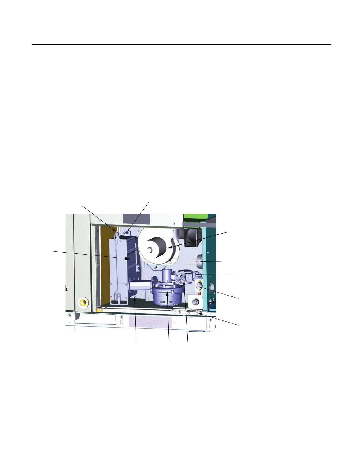
Figure 56. NOx burner component layout
Flame sensor (shown for 90k furnace)
Flame rollout switch
Inducer motor
Pressure switch
Gas valve
Premix
blower
Spark
electrode
Note: Illustration is shown without Gas Heat Access Door and Right Center Post.
NOx
burner box
Field connection
- 1/2" npt(f)
Low temperature
ambient cutoff
switch
E box 24V
for gas valve