Installation
RT-SVX21AC-EN 35
3. Lift the tube and bracket from the downflow duct
opening. Rotate the tube and bracket assembly 180
degrees ensuring that the holes on the copper sensing
tube face away from the unit and face the return air
ductwork. For screw location, reference the following
two figures.
Note: Che
ck to insure that the flexible tubing lies flat on
the base pan surface.
4. Slide the top bracket down the copper sensing tube.
For YSC036G-060, and YHC036-037E units insert the
tab on the left side into the slot on the indoor coil block
off and secure the right side of the bracket with one of
the 3 screws removed in step 2. Refer to Figure 51,
p. 35. For YHC047E-067E, YHC048E/F-060E/F,
YSC072H-120H and YHC(
072E/F, 074F-120F) units
secure the tab on left side to
the indoor coil block off
with one of the screws removed in step 2 and secure
the right side of the bracket with one of the screws
removed from the access panel. Refer to Figure 52,
p. 35.
5. Using the remaining 2 screws removed in step 2,
sec
ure the bottom bracket. Refer to Figure 51, p. 35.
Note: L
arger diameter holes on bottom bracket line up
with the di
mples on the rear panel. The smaller
diameter holes line up with the screw holes in the
rear panel.
Air-Fi
®
Wireless Communication
Interface
The factory installed wireless communications interface is
installed in the downflow discharge position.
If a unit is to be converted to horizontal discharge, the
following conv
ersion must be performed:
1. If the unit has an economizer, it must be pulled out in
the operati
ng position.
2. Remove the screw from the mounting
bracket. Refer to
downflow view for screw and bracket location.
3. Mount the bracke
t in the horizontal discharge location.
Refer to horizontal view for screw and bracket location.
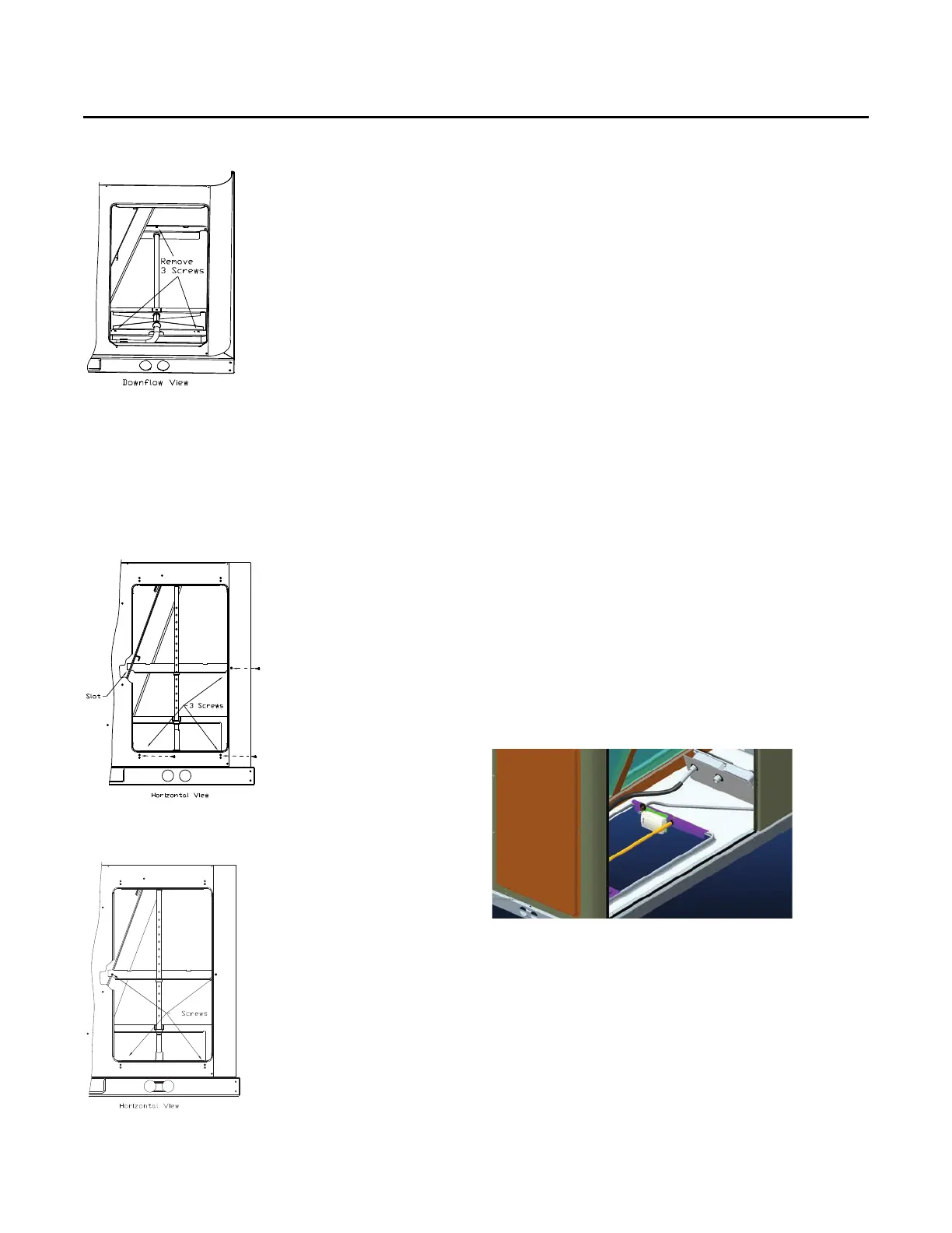
Figure 50. Downflow view
Figure 51. Horizontal view 1
Figure 52. Horizontal view 2
Figure 53. Wireless communication interface -
downflow