Sequence of Operation
60 RT-SVX21AC-EN
Electromechanical Evaporator Fan
Operation (for Cooling Only Units)
When the thermostat fan selection switch is set to the
“Auto” position, the thermostat energizes the indoor fan
relay coil (F) to start the indoor fan motor (IDM). The fan
relay (F) de-energizes after the cooling requirement has
been satisfied. When the heating cycle is terminated, the
indoor fan relay (F) coil is de-energized with heater
contactors.
When the thermostat fan selection switch
is set to the
“On” position, the thermostat keeps the indoor fan relay
coil (F) energized for continuous fan motor operation.
Economizer Set-Up
Adjusting the minimum position potentiometer located on
the unit economizer actuator (ECA) sets the required
amount of ventilation air.
Ambient temperature is controlling the economizing cycle
by
sensing
the outside air dry bulb temperature. The
following table lists the selectable dry bulb values by
potentiometer setting.
Electromechanical Control Cooling with
an Economizer
The economizer is utilized to control the zone temperature
providing the outside air conditions are suitable. Outside
air is drawn into the unit through modulating dampers.
When cooling is required and economizing is possible, the
unit econom
izer actuator (ECA) opens the economizer
damper. The ECA continues to modulate the economizer
damper open/closed to keep the mixed air temperature in
the 50ºF to 55ºF range.
The thermostat will close the Y2 contacts to turn on
con
tactor (CC1) if mechanical cooling is required.
If economizing is not possible, the ECA drives the damper
to the mini
mum position setpoint when the indoor fan
relay (F) is energized and allows mechanical cooling
operation.
Electromechanical Control Heating
Operation (for Cooling Only Units)
When the system switch is set to the “Heat” position and
the zone temperature falls below the heating setpoint, the
thermostat closes W1 contacts the first stage electric heat
contactor (AH or AH and CH) is energized. If the first stage
of electric heat can not satisfy the heating requirement, the
thermostat closes W2.
When the W2 contacts close, the second stage electric h
eat
contactor (BH) is energized, if applicable. The thermostat
cycles both the first and second stages of heat “On” and
“Off” as required to maintain the zone temperature
setpoint.
Electromechanical Control Heating
Operation (for Gas Units)
When the system switch is set to the “Heat” position and
the zone temperature falls below the heating setpoint, the
Ignition module (IGN) initiates a heat cycle.
Ignition Module Low, Medium and High
Heat
Two-stage (IGN) runs self-check (including verification
that the gas valve is de-energized). (IGN) checks the high-
limit switches (TC01 and TC02) for normally closed
contacts, the pressure switch (PS) for normally open
contacts, and the flame rollout (FR) switch for continuity.
(IGN) energizes inducer blower on high speed to check
pressure switch closure.
If the pressure switch is close
d, the inducer blower starts
a 20 second pre-purge (15 seconds on high speed followed
by 5 seconds on low speed).
If the pressure switch (PS) is still open, the inducer blower
wi
ll conti
nue to be energized on high speed until pressure
switch closure.
After pre-purge completes,
the (IGN) energizes the
first
stage of the gas valve, initiates spark for 2 seconds
minimum, 7 seconds maximum (ignition trial) and detects
flame and de-energizes spark. From this point, a fixed 45
second indoor blower delay on timing starts.
After the indoor blower delay on
is completed, the (IGN)
ener
gizes the indoor blower. The (IGN) enters a normal
operating loop where all inputs are continuously
monitored. If the first stage of gas heat can not satisfy the
heating requirement, the thermostat closes W2. The (IGN)
energizes the second stage of the gas valve and the second
stage of inducer blower.
When the zone thermostat is satisfied, the (IGN) de-
e
nergizes the gas valve. The (IGN) senses loss of flame.
The (IGN) initiates a 5 second inducer blower post purge
and 90 second indoor blower delay off at current speed.
The (IGN) de-energizes the inducer blower at the end of the
post purge. The (IGN) de-energizes the indoor blower at
the end of the selected indoor blower delay off.
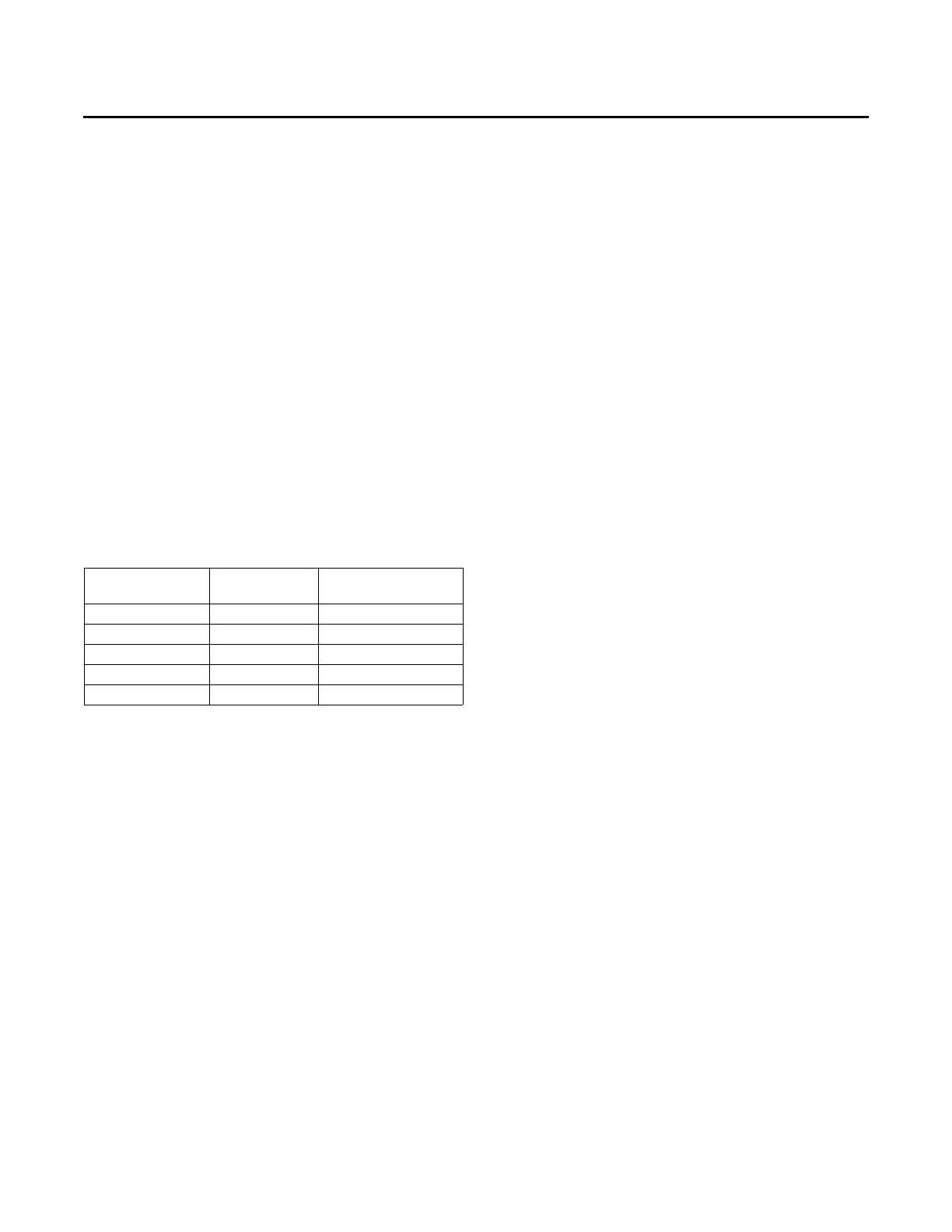
Table 20. Potentiometer settings
Potentiometer
Setting Dry Bulb Reference Enthalpy
A 73°F (22.8ºC) 27 Btu/lb (63 kJ/kg)
B 70°F (21.1ºC) 25 Btu/lb (58 kJ/kg)
C 67°F
(a)
(19.4ºC)
(a) Factory settings
23 Btu/lb (53 kJ/kg)
D 63°F (17.2ºC) 22 Btu/lb (51 kJ/kg)
E 55ºF (12.8ºC) 19 Btu/lb (44 kJ/kg)