Installation
38 RT-SVX21AC-EN
Condensate Drain Configuration
An evaporator condensate drain connection is provided
on each unit. Refer to the ductwork section in the
Installation chapter for the appropriate drain location.
The condensate drain pan is factory installed to drain
condensate to the back side of the unit. Refer to the
ductwork section in the
Installation chapter for the
drawings. It can be converted to drain condensate out the
front side of the unit or through-the-base.
To convert drain condensate out the front of
unit:
1. Remove evaporator access panel and supply air access
panels.
2. Remove the support panel that the condensate drain
pan exits thro
ugh.
3. Slide the condensate drain pan out of the unit and
ro
tate 180°.
4. Slide th
e condensate drain pan back into the unit, align
the drain with the grom
meted opening in the rear
support panel and push until the coupling is seated in
the grommet.
5. Replace the front support panel by aligning the panel
with tabs
in the raceway. Align
the condensate drain
pan support in the grommeted hole as the panel is put
in place.
6. Replace evaporator access panel and supply air access
pa
nels.
To convert drain condensate through-the base
of unit:
1. Remove evaporator access panel and supply air access
panels.
2. Remove the support panel that the condensate drain
pan exits thro
ugh.
3. Slide the condensate drain pan out of the unit.
4. Place on a level surface in the position
it was removed
from the un
it.
5. Remove the plug knockout in the bottom of the drain
pan
to convert it to through-the
-base drainage.
6. Plug the original condensate drain opening with a field
supplied 3/4-inch
NPT plug.
7. Slide the condensate drain pan back into the unit, align
the d
rain support wi
th the grommeted opening in the
rear support panel and push until the support is seated
in the grommet.
8. Replace the front support panel by aligning the panel
with tabs in the
raceway. Align the plugged
condensate drain pan coupling in the grommeted hole
as the panel is put in place.
9. Replace evaporator access panel and supply air ac
cess
panels
.
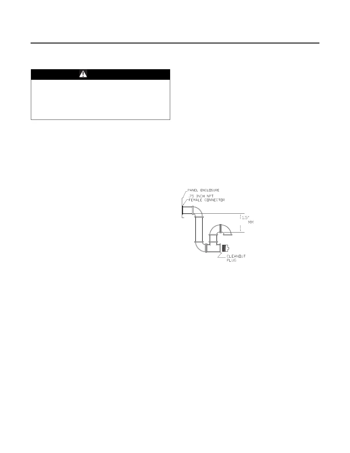
A condensate trap must be installed at the unit due to the
drain conne
ction being on the “negative pressure” side of
the fan. Install the P-Trap using the guidelines in Figure 57,
p. 38.
A condensate drain line must be connected to the p-trap.
P
itch th
e drain lines at least 1/2 inch for every 10 feet of
horizontal run to assure proper condensate flow. Do not
allow the horizontal run to sag causing a possible double-
trap condition which could result in condensate backup
due to “air lock”.
Drain Pan Removal (Units with Condensate
Overflow Switch Option)
Before drain pan removal, the switch wire must be
disconnected from wire tie on panel and/or any tape
before drain pan can be removed.
Care must be taken so the wire does not catch on the
bo
ttom of indoor coil or any protrusion.
Note: Whe
n reve
rsing the drain pan, on some units, the
condensate overflow switch will need to be moved
to the second hole in its bracket to avoid contact
with headers or indoor coil.
Filter Installation
The quantity of filters is determined by unit size. Access to
the filters is obtained by removing the filter access panel.
Refer to the unit Service Facts (shipped with each unit) for
filter requirements.
Note: Do
not operate the unit without filters.
WARNING
Hazardous Voltage!
Failure to disconnect power before servicing could
result in death or serious injury. Disconnect all electric
power, including remote disconnects before servicing.
Follow proper lockout/tagout procedures to ensure the
power can not be inadvertently energized.
Figure 57. Condensate trap installation
38.1