Sequence of Operation
RT-SVX21AC-EN 65
Note: The RTRM is designed to maintain a selectable
supply air temperature of 40°F to 90°F with a +/-
3.5°F deadband. However, to reduce the risk of
evaporator coil freeze-up in Precedent and Voyager
Light Commercial applications, supply air
temperature should not be set below 50°F.
VHR Relay Output
During unoccupied mode, daytime warm-up (DWU),
morning warm-up (MWU) and heating mode the Supply
Fan will operate at 100% of user set maximum airflow. All
VAV boxes must be opened through an ICS program or by
the VHR wired to the VAV boxes. The RTRM will delay
100% fan operation approximately 6.5 minutes when
switching from occupied cooling mode to a heating mode.
Zone Temperature Control without a Night
Setback Panel or ICS - Unoccupied Cooling
When a field supplied occupied/unoccupied switching
device is connected between RTRM J6-11 and RTRM J6-
12, both the economizer and the mechanical cooling will
be disabled.
Zone Temperature Control without a Night
Setback Panel or ICS - Unoccupied Heating
When a field supplied occupied/unoccupied switching
device is connected between RTRM J6-11 and J6-12 and
DWU is enabled, the zone temperature will be controlled
at 10°F below the Morning Warm-up setpoint, but not less
than 50°F, by cycling one or two stages of either gas or
electric heat, whichever is applicable.
Morning Warm-up (MWU) Control
Morning Warm-up is activated if the zone temperature is
at least 1.5°F below the MWU setpoint whenever the
system switches from Unoccupied to Occupied status. The
MWU setpoint may be set from the unit mounted
potentiometer or a remotely mounted potentiometer. The
setpoint ranges are from 50°F to 90°F. When the zone
temperature meets or exceeds the MWU setpoint, the unit
will switch to the “Cooling” mode. The economizer will be
held closed during the morning warm-up cycle.
Daytime Warm-up (DWU) Control
Daytime Warm-up is applicable during occupied status
and when the zone temperature is below the initiation
temperature. It can be activated or deactivated through
ICS or a night setback zone sensor. If ICS or a night setback
zone sensor is not utilized, DWU can be activated by
setting the DWU enable DIP switch (RTAM) to ON and
supplying a valid morning warm-up setpoint.
The unit is shipped with a Morning Warm-up setpoint
configured an
d the Daytime Warm-up function is activated
(switch on). Opening the DWU enable switch will disable
this function.
If the system control is local, the DWU initiation setpoint is
3°F be
low the Mo
rning Warm-up setpoint. The
termination setpoint is equal to the Morning Warm-up
setpoint.
If the system control is remote (Tracer®), the DWU
se
tpoint
is equal to the Tracer® Occupied heating setpoint.
The initiation and termination setpoints are selectable
setpoints designated by Tracer®.
When the zone temperature meets or exceeds the
term
ination
setpoint while the unit is in an Occupied,
“Auto” Mode or switched to the “Cooling” Mode, the unit
will revert to the cooling operation.
If an Occupied “Heating” Mode is selected, the unit will
only
function with
in the DWU perimeters until the system
is switched from the “Heat” Mode or enters an
Unoccupied status.
Note: Wh
en a LCI is installed on a VAV unit, the MWU
setpoint located on the RTAM board is ignored. The
MWU and DWU setpoints come from the higher
priority LCI-R DAC.
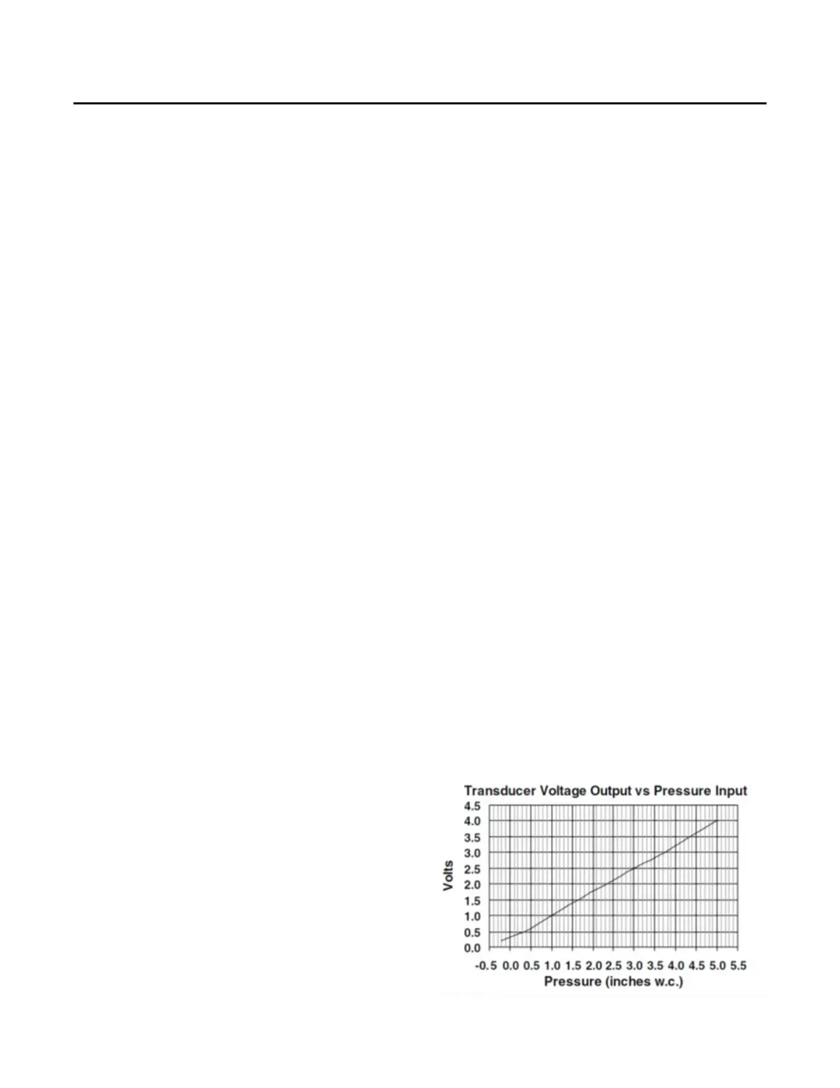
Supply Duct Static Pressure Control
The supply duct static pressure is measured by a
transducer with a 0.25 to 2.125 Vdc proportional output
which corresponds to an adjustable supply duct static
pressure of 0.3" w.c. to 2.5" w.c. respectively with a
deadband adjustment range from 0.2" w.c. to 1.0" w.c. The
setpoint is adjustable on the RTAM Static Pressure
Setpoint potentiometer or through ICS.
Traditional VAV Standalone Operation
If a traditional VAV unit is required to operate without ICS,
BAS or other “front end” controller, a jumper must be
placed between J6-2 and J6-4 of the RTRM to allow local
standalone control.
Example:
Supply Duct Static setpoint = 2.0" w.c. (RTAM)
Deadband = 0.2" w.c. (RTAM)
Duct Static Control Range = 1.9" w.c. to 2.1" w.c.
Figure 74. Transducer voltage output vs. pressure input