Sequence of Operation
RT-SVX21AC-EN 63
Once the supply fan has started, determine the total
system airflow (CFM)
1. Measure the DC voltage across harness test terminals.
Us
ing the fan rpm table shown above, determine RPM
correlated to measured voltage.
2. If the required CFM is too low, (external static pressure
i
s high
causing motor HP output to be below table
value),
a. Relieve supply and/or return duct static.
b. Change indoor fan speed and repeat steps 1 and 2.
• To Increase/Decrease Fan RPM turn DA COOL_FAN
SPD on the RTOM clockwise/counter-clockwise.
3. If the required CFM is too high, (external static
p
ressu
re is low causing motor HP output to be above
table value), change indoor fan speed and repeat steps
1 and 2.
• Stop the SERVICE TEST, turn
the main power
disconnect s
witch to the “Off” position and reconnect
Economizer 4-pin power connector if disconnected for
this procedure.
Proceed to the next component start-up procedure.
Electromechanical Control: Using the Service Test
Guide perform the proper test mode connections.
Once the supply fan
has star
ted, determine the total
system airflow (CFM) by (ReliaTel™/Electromechanical):
1. Measure the amperage at the supply fan contactor and
compare it with the full load amp (FLA) rating
for the
evaporator motor stamped on the unit nameplate.
a. Calculate the theoretical BHP using (Actual Motor
A
mps
/Motor Nameplate Amps) X Motor HP.
b. Using the fan performance tables in the unit Service
Facts, plot the actual RPM (step 1) and the BHP (step
2a) to obtain the operating CFM.
2. If the required CFM is too low, (external static pressure
i
s hi
gh causing motor HP output to be below table
value),
a. Relieve supply and/or return duct static.
b. Change indoor fan speed and repeat steps 1 and 2.
• For ECM board: To Increase/Decrease Fan RPM:
a. Push and hold the SET button for 3 sec.
Board will
disp
lay Motor 1 parameter name: Hi 1.
b. Slow push SET again to display the parameter’s
current
value =7.50 volts.
c. Push on + or – button to adjust parameter
to desired
va
lue = XXX volts.
d. Push and hold SET button for 3 sec to “save” the
value. After sav
e is complete, Hi 1 will show again.
e. After the voltage Hi 1 is successfully changed, the
displa
y sequence will be:
MTR 1---> XXX -----> MTR2 ----->
0.00----->FST1---->ON/
OFF----->FST2------>ON/OFF------->EhEn--
--->ON/OFF
The motor will ramp up or down to adjust to the input
signal. U
sing the fan rpm table above, determine RPM
correlated to displayed voltage.
• If the required CFM is too high, (external static
pre
ssure is low
causing motor HP output to be above
table value), change indoor fan speed and repeat steps
1 and 2.
• To stop the SERVICE TEST, t
urn the m
ain power
disconnect switch to the “Off” position or proceed to
the next component start-up procedure.
Units with Constant CFM Direct Drive
Indoor Fan
Much of the systems performance and reliability is closely
associated with, and dependent upon having the proper
airflow supplied both to the space that is being
conditioned and across the evaporator coil. The indoor fan
provides a constant CFM base on voltage output for the
potentiometer on the RTOM board. Before starting the
SERVICE TEST, set the minimum position setpoint for the
economizer to 0% using the setpoint potentiometer
located on the Economizer Control (ECA), if applicable.
ReliaTel™ Control. Using the Service Test Guide in
Table 16, p. 51, momentarily jump across the Test 1 and
Test 2 terminals on LTB1 one time to start the Minimum
Ventilation Test.
Once the supply fan has started, determine
the total
system airflow (CFM) by:
1
. Measure the DC voltage across pins TP1 and ground
(screw on corner o
f RTOM board). Lookup desired CFM
using the voltage CFM table shown on the access panel
label or in the unit Service Facts; record corresponding
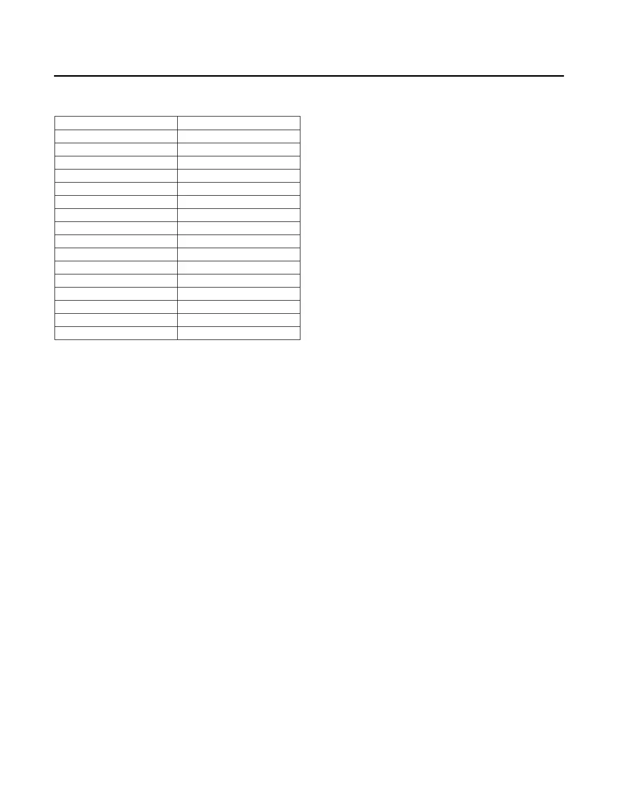
3.75 775
4 845
4.25 912
4.5 976
4.75 1044
5 1115
5.25 1203
5.5 1253
5.75 1312
6 1368
6.25 1425
6.5 1475
6.75 1533
7 1581
7.25 1615
7.5 1615
Table 22. Direct drive plenum fan settings (rpm vs.
voltage) (continued)
Potentiometer Voltage Motor RPM