Home
TriangleTube
Boiler
Instinct Series
TriangleTube Instinct Series Installation & Maintenance Manual
4
of 1
of 1 rating
112 pages
Give review
Manual
Specs
To Next Page
To Next Page
To Previous Page
To Previous Page
Loading...
22
C
HAPTER 4
CHAPTER
4 - BOILER PIPING
P G
System
Supply
System
Return
12"
Max.
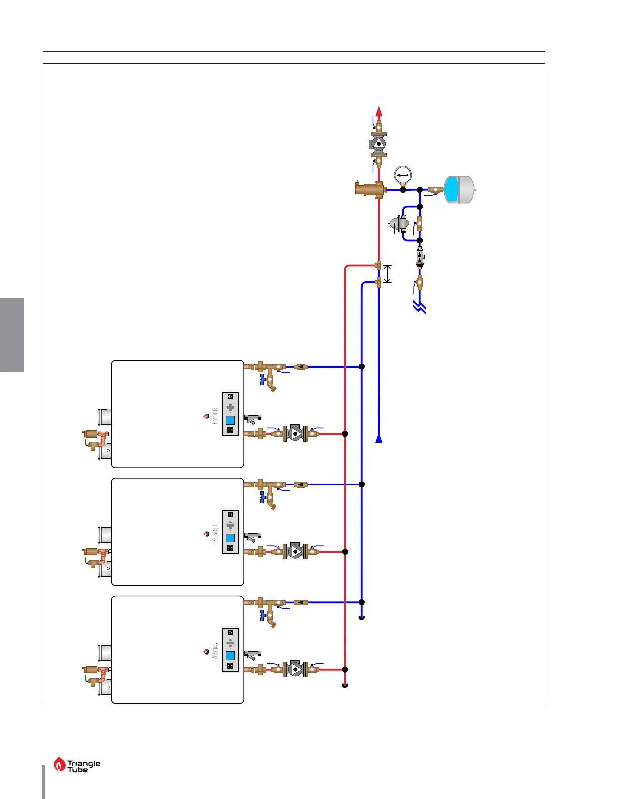
Fig
. 13 - Multiple PRESTIGE Solo B
oiler Piping - P
rimar
y / Secondary
Consult the PRESTIGE A
CV
-
Max Control Supplement
for information on wiring
and configuring the boilers
using the built-in Casc
ade
function
NO
TICE
33
35
Table of Contents
Default Chapter
3
Table of Contents
3
Product and Safety Information
11
Chapter 1 - Pre-Installation Requirements
13
Code Compliance
13
Determining Product Location
13
Boiler Freeze Protection Feature
14
Boiler Replacement
14
Recommended Clearances
14
Residential Garage Installations
14
Chapter 2 - Combustion Air & Venting
15
Combustion Air Contamination
15
Ventilation and Combustion Air Requirements - Direct Vent
16
Ventilation and Combustion Air Requirements - Category IV
16
Methods of Accessing Combustion Air into a Space - Category IV
17
Indoor Combustion Air
17
Outdoor Combustion Air
17
Fig. 1 - All Combustion Air from Adjacent Indoor Spaces through Indoor Combustion Openings
17
Fig. 2 - All Combustion Air from Outdoors through One Permanent Air Opening
17
Combination of Indoor and Outdoor Combustion Air
18
Combustion Air and Vent Piping
18
Fig. 3 - All Combustion Air from Outdoors through Ventilated Attic
18
Fig. 4 - All Combustion Air from Outdoors through Horizontal Ducts
18
Removal of an Existing Boiler from a Common Vent System
19
Carbon Monoxide Detector Installation
20
Commonwealth of Massachusetts Installation Requirements
20
Installation of Carbon Monoxide Detectors
20
Approved Carbon Monoxide Detectors
20
Signage
20
Inspection
20
Manufacturer Requirements - Gas Equipment Venting System Provided
21
Manufacturer Requirements - Gas Equipment Venting System Not Provided
21
Chapter 3 - Unit Preparations
23
Handling Instructions
23
Wall Mounting Installation
23
Wall Mounting Guidelines
23
Stud Walls - Installation
24
PRESTIGE solo 80/110/155/175/250
24
PRESTIGE solo 299/399
24
Wall Bracket Installation - Solid Walls
24
Boiler Mounting
24
Chapter 4 - Boiler Piping
25
General Piping Requirements
25
Pressure Relief Valve
25
Fig. 5 - Pressure Relief Valve and Boiler Drain Valve Installation
25
Boiler Air Vent
26
Low Water Cutoff Device
26
Fig. 6 - Piping Component Legend
26
Additional Limit Control
27
Backflow Preventer
27
Boiler System Piping Applications
27
Fig. 7 - Near Boiler Piping - Diaphragm Expansion Tank
27
Expansion Tank and Makeup Water
28
Diaphragm Expansion Tank
28
Closed-Type Expansion Tank
28
Fig. 8 - Near Boiler Piping - Closed Type Expansion Tank
28
Circulator
29
Sizing Primary Piping
29
Domestic Hot Water System Piping
29
System Piping - Zone Circulators
29
System Piping - Zone Valves
29
System Piping - through Boiler
29
Fig. 9 - System Piping - Zoning with Zone Circulators
30
Fig. 10 - System Piping - Zoning with Zone Valves
31
Fig. 11 - System Piping - Multiple Zone Valve with Single System/Boiler Circulator
32
Fig. 12 - System Piping - Single Zone System with Single System/Boiler Circulator
33
Fig. 13 - Multiple PRESTIGE solo Boiler Piping - Primary / Secondary
34
System Piping - Radiant Heating
35
System Piping - Special Application
35
System Piping - Multiple Units Installation
35
Chapter 5 - Installing Vent/Combustion Air & Condensate Drain
37
Installing Vent and Combustion Air
37
Installing Condensate Drain Assembly
37
Fig. 14 - Condensate Drain Assembly
38
Chapter 6 - Gas Piping
39
Gas Supply Piping Connection
39
Fig. 15 - Recommended Gas Supply Piping
39
Natural Gas
40
Pipe Sizing
40
Supply Pressure Requirements
40
Propane Gas
41
Pipe Sizing
41
Supply Pressure Requirements
41
Fig. 16 - Gas Valve / Venturi Assembly - PRESTIGE solo 80-110
42
Fig. 17 - Gas Valve / Venturi Assembly - PRESTIGE solo 155/175/250
42
Fig. 18 - Gas Valve / Venturi Assembly - PRESTIGE solo 299 /399 (Œ)
43
Fig. 19 - Gas Valve / Venturi Assembly - PRESTIGE solo 299/399 ( )
43
Chapter 7 - Internal Wiring
45
General Requirements
45
Fuse Locations
45
Fig. 20 - Acvmax Control Module Fuse Location
45
Fig. 21 - Prestige solo Boiler Factory Wiring
46
Chapter 8 - External Wiring
47
General Requirements
47
Line Voltage Connections
47
Circulator Wiring
47
Flame Status & Alarm Wiring
47
Fig. 22 - Terminal Strip Location
47
Low Voltage Connections
48
Thermostat Wiring
48
Fig. 23 - Low Voltage Connections
48
Outdoor Sensor Wiring
49
Domestic Hot Water Wiring
49
Additional Boiler Limits
49
External Modulation Control
49
System Sensor Wiring
49
Cascade Wiring
50
Modbus Wiring
50
Fig. 24 - Typical Zone Panel Wiring to PRESTIGE with Zone Valves
50
Fig. 25 - Typical Zone Panel Wiring to PRESTIGE with Zone Circulators
51
Chapter 9 - Acvmax Operation
53
Acvmax Navigation
53
Fig. 26 - Acvmax User Interface
53
Acvmax Menu Structure
54
Home Screen
55
Status Line Messages
56
Main Menu
57
EZ Setup
57
Heating EZ Setup
58
Select CH Demand (no Outdoor Sensor Connected)
58
Select CH Demand (Outdoor Sensor Connected)
59
Domestic Hot Water EZ Setup
60
EZ Setup Reset
61
Display EZ Setup
61
CH/DHW Operation
62
Boiler Information
62
Information Items
63
Lockout Screen
64
Manual Reset Lockouts
65
Automatic Reset Blocking Lockouts
66
Chapter 10 - Start-Up Preparation
67
Boiler System Fluid Requirements
67
Boiler Fluid Ph Level 6.0 to 8.0
67
Boiler Fluid Hardness Less than 7 Grains
67
Chlorinated Water
67
Flush Boiler to Remove Sediment
67
Cleaning of Old Boiler/System
67
Cleaning of New Boiler/System
67
Check and Test Antifreeze
68
Use of Antifreeze in the Boiler System
68
Filling the Boiler System
68
Check Low Water Cut-Off Device
68
Check for Gas Leaks
69
Check Thermostat Circuit
69
Inspect Condensate Drain Assembly
69
Chapter 11 - Start-Up Procedures
71
Final Checks before Start-Up
71
PRESTIGE solo Start-Up
71
Check the PRESTIGE solo and System
71
Check Boiler Piping
71
Check Vent and Combustion Air Piping
71
Verify Carbon Monoxide Detector
71
Check Gas Piping
72
Verify Flame Pattern and Combustion
72
Measure Input - Natural Gas Only
73
Test High Temperature Limit
73
Chapter 12 - Outdoor Reset Control
75
Mounting the Outdoor Sensor
75
Wiring the Sensor
75
Chapter 13 - External Modulating Control
77
Wiring the Modulating Controller
77
Acvmax Programming
77
Programming of External Modulating Control
77
Chapter 14 - Check-Out Procedures
79
Chapter 15 - Installation Record
81
Chapter 16 - Maintenance Schedules
83
Service Technician
83
Owner Maintenance
83
Chapter 17 - Maintenance Procedures
85
Service Technician Maintenance Procedures
85
Reported Problems
85
Check Surrounding Area
85
Inspect Burner Area
85
Check System Piping
85
Clean Condensate Drain Assembly
85
Check Ventilation Air Openings
86
Inspect Vent and Combustion Air Piping
86
Check Boiler System
86
Check Expansion Tank
86
Check Boiler Relief Valve
86
Inspection of Ignitor
86
Check Ignition Cable and Ground Wiring
87
Check Control Wiring
87
Check Control Settings
87
Perform Start-Up and Checkout Procedures
87
Check Burner Flame
87
Check Flame Signal
87
Check Combustion Levels
88
Check Flue Gas Temperature
88
Clean Heat Exchanger
88
Check Carbon Monoxide Detectors
88
Review with Owner
88
Torque Specifications Table
88
Chapter 18 - Replacement Parts
89
Fig. 27 - PRESTIGE solo 80/110 Jacket Components
89
Fig. 28 - PRESTIGE solo 155/175/250 Jacket Components
90
Fig. 29 - PRESTIGE solo 299/399 Jacket Components
91
Fig. 30 - PRESTIGE solo 80/110 Internal Components
92
Fig. 31 - PRESTIGE solo 155/175/250 Internal Components
93
Fig. 32 - PRESTIGE solo 299/399 (Œ) Internal Components
94
Fig. 33 - PRESTIGE solo 299/399 ( ) Internal Components
95
Fig. 34 - PRESTIGE solo 80/110 Burner Components
96
Fig. 35 - PRESTIGE solo 155/175/250 Burner Components
97
Fig. 36 - PRESTIGE solo 299/399 (Œ) Burner Components
98
Fig. 37 - PRESTIGE solo 299/399 ( ) Burner Components
99
Fig. 38 - PRESTIGE solo Control & Display Enclosures
100
Chapter 19 - Product Specifications
101
Fig. 39 - Front View PRESTIGE solo 80/110
102
Fig. 40 - Right Side View PRESTIGE solo 80/110
103
Fig. 41 - Front View PRESTIGE solo 155/175/250
104
Fig. 42 - Right Side View PRESTIGE solo 155/175/250
105
Graph 1 - Pressure Loss through Boiler - Taco Circulators
108
Graph 3 - Pressure Loss through Boiler - Taco Circulators
109
Graph 5 - Pressure Loss through Boiler - Taco Circulators
110
Other manuals for TriangleTube Instinct Series
User's Information Manual
48 pages
4
Based on 1 rating
Ask a question
Give review
Questions and Answers:
Need help?
Do you have a question about the TriangleTube Instinct Series and is the answer not in the manual?
Ask a question
TriangleTube Instinct Series Specifications
General
Brand
TriangleTube
Model
Instinct Series
Category
Boiler
Language
English
Related product manuals
TriangleTube Instinct SOLO 110
128 pages
Instinct Solo Series
44 pages
TriangleTube prestige
46 pages
TriangleTube PSRKIT25
14 pages
TriangleTube Prestige Solo
44 pages
TriangleTube PRESTIGE Series
48 pages
TriangleTube Prestige Solo 60
12 pages
TriangleTube CHALLENGER CC 85
92 pages
TriangleTube Prestige Solo 110
14 pages
TriangleTube Prestige SOLO 299
12 pages
TriangleTube Prestige SOLO 155
14 pages
TriangleTube Prestige Solo 175
14 pages
 Loading...