36
CHAPTER 8
CHAPTER 8 - EXTERNAL WIRING
The Alarm output is typically used to provide lockout
status to an external monitoring system. The Alarm
output will provide 0VAC when the PRESTIGE Solo is
not in a lockout and 110VAC when the PRESTIGE Solo is
in a lockout. The types of lockouts which will cause the
Alarm output to activate are adjustable in the Installer
Menu. Consult the PRESTIGE ACVMax Control Supple-
ment for information on this setting.
1. Connect the external monitoring device to the line
voltage terminals located internally in the lower
right corner, as shown in Fig. 22 on page 35.
The circulator, flame, and alarm outputs are pro-
tected by fuses on the ACVMax control module.
The total combined amp draw of the CH, DHW,
and Flame outputs must not exceed 4 amps at
any time for the Solo 80 through 250, or 3 amps
at any time for the Solo 299 & 399. The total com-
bined amp draw of the P3, P4, and Alarm outputs
must not exceed 5 amps at any time for all Pres-
tige models. Use an isolation relay to lower the to-
tal combined amp draw if exceeding these limits..
8.5. Low Voltage Connections
Line and Low Voltage wiring should be separated to
prevent possible electrical noise on the low voltage cir-
cuits. Line and Low Voltage wiring should use separate
electrical knockouts on the PRESTIGE Solo cabinet and
should remain separated inside the PRESTIGE Solo.
CH and DHW call connections to the PRES-
TIGE Solo require a dry contact with no external
voltage present. Ensure no external voltage is
present on each set of wires before connecting
to the PRESTIGE Solo. If external voltage is pres-
ent, the use of an isolation relay is required to
prevent damage to the ACVMax controller.
NOTICE
NOTICE
8.6. Thermostat Wiring
The ACVMax control has two thermostat call inputs for
multiple zone / temperature systems. This allows each
call to have its own outdoor reset curve and maximizes
the eciency of the system.
Simultaneous CH1 and CH2 calls will result
in the PRESTIGE Solo operating at the highest
target temperature. The use of a mixing device
on the lower temperature zone(s) may be re-
quired to protect the lower temperature zone(s)
from damage. The ACVMax control includes a
mixing valve function which can operate a mix-
ing valve in a dual temperature system. Consult
the PRESTIGE ACVMax Control Supplement for
additional information on this function. .
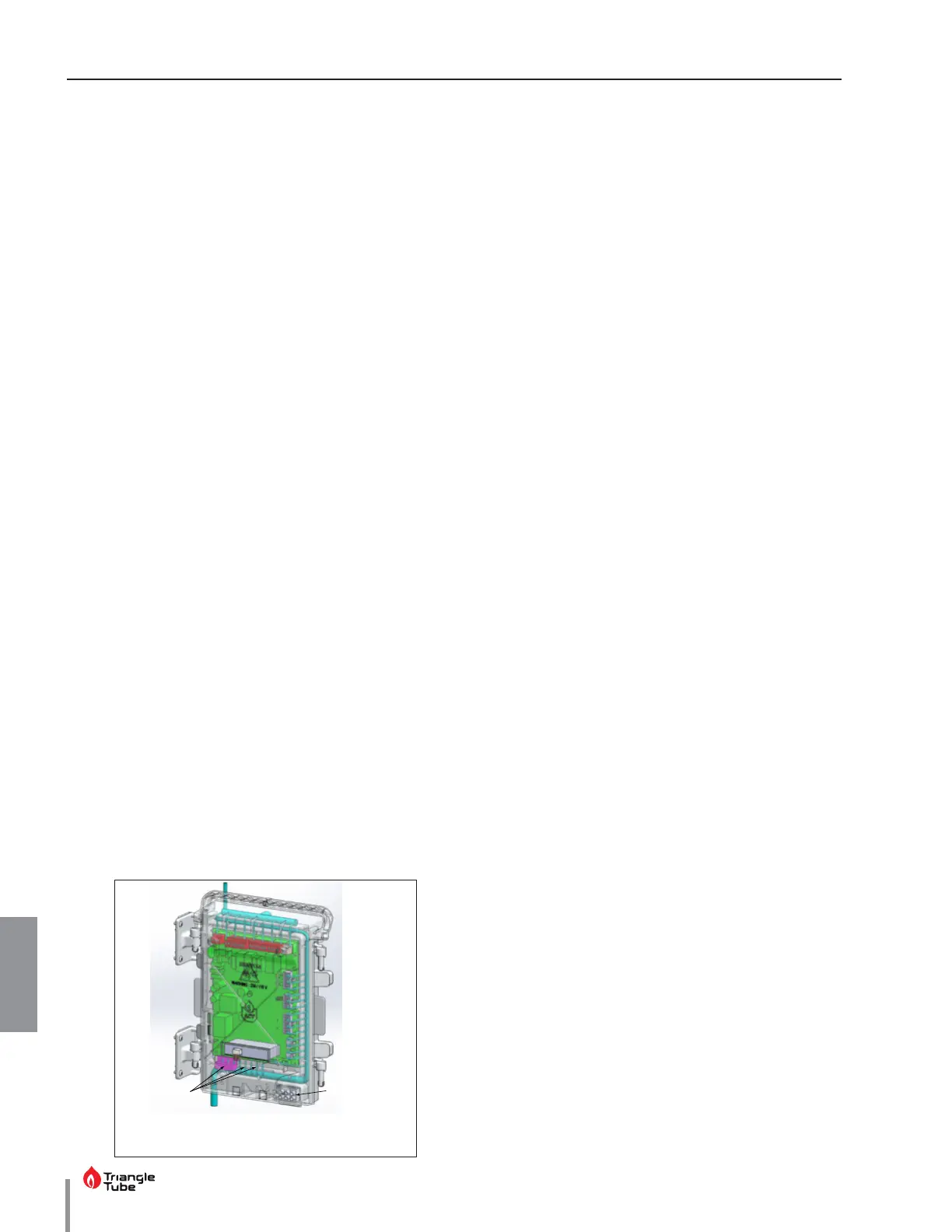
1. Connect the room thermostat or dry contact zone
valve end switch wires to low voltage terminals X6-
3&4 or X5-5&6 located at the bottom of the ACVMax
control module as shown in Fig 22 below.
2. Follow thermostat manufacturer’s instructions for
proper installation. Thermostat should be located
on an inside wall away from any heat or cold inu-
ences such as drafts, lights, replaces, etc.
3. Set the thermostat anticipator (If applicable) as fol-
lows:
• Set for 0.2 amps when wired directly to the
PRESTIGE Solo.
• Set to match the electrical power requirements
of the connected device when wired to zone
relays or other devices. Refer to the relay man-
ufacturer’s specications and the thermostat
instructions for additional information on antic-
ipator setting.
The use of power stealing thermostats
which draw their power from the PRESTIGE Solo
can lead to erratic or unpredictable operation.
NOTICE
NOTICE
External Limit
Terminals
Low Voltage
Terminals
Fig. 23 - Low Voltage Connections
 Loading...