27
CHAPTER 5
CHAPTER 5 - INSTINCT COMBI UNITS - DOMESTIC PIPING
5.1. Domestic Piping Pressure Relief Valve
To reduce risk of excessive pressures and
temperatures in the water heater, install tem-
perature and pressure protective equipment
required by local codes, but no less than a com-
bination temperature and pressure relief valve
certified by a nationally recognized testing lab-
oratory that maintains periodic inspection of
production of listed equipment or materials, as
meeting the requirements for Relief Valves and
Automatic Gas Shutoff Devices for Hot Water
Supply Systems, ANSI Z21.22. This valve must
be marked with a maximum working pressure
of the water heater.
Failure to comply with this instruction can re-
sult in minor property damage, or injury.
The INSTINCT Combi domestic circuit must be protect-
ed with a pressure relief valve (150 psi).
5.1.1 Standard Installation
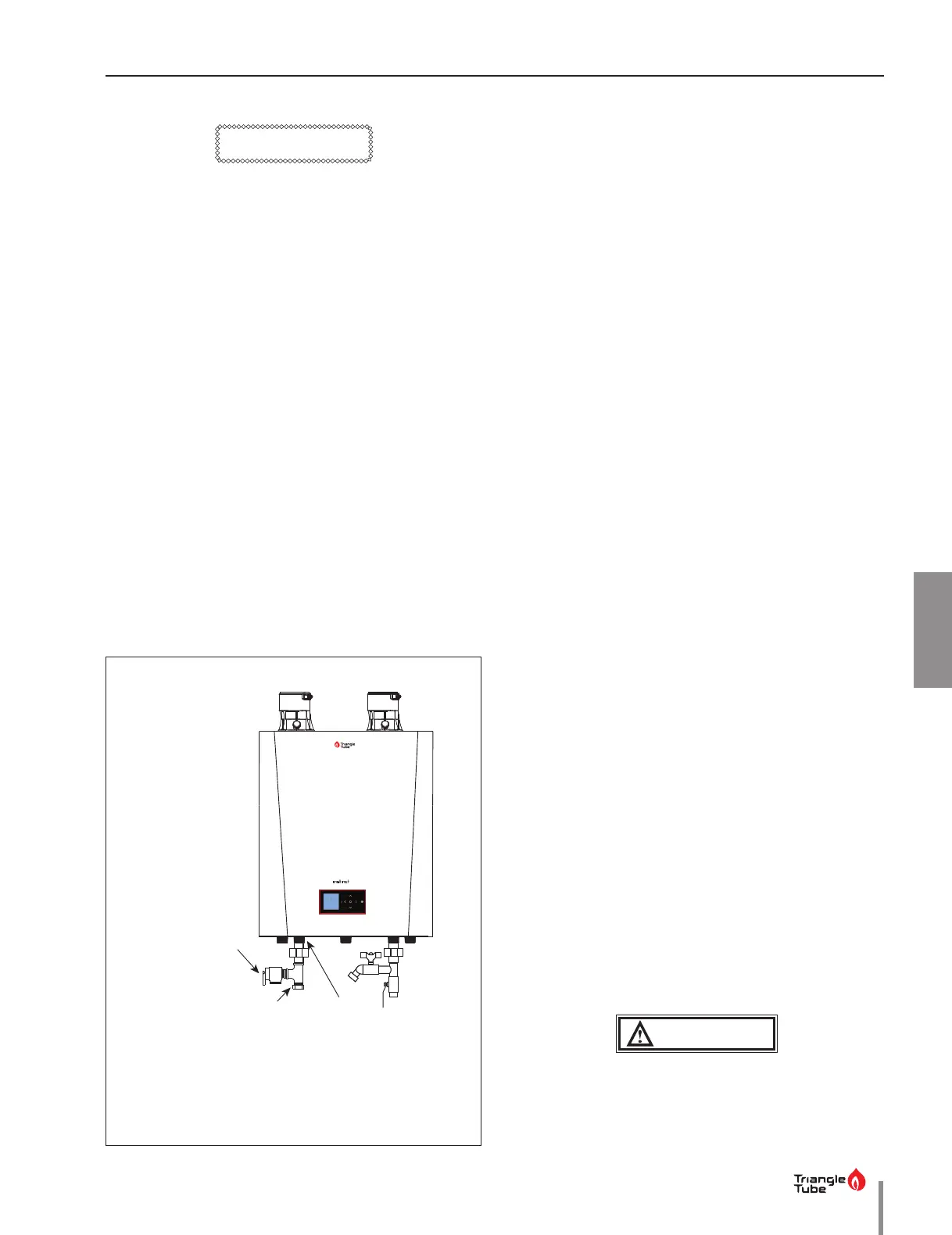
Install pressure relief valve as shown in Fig. 15.
CAUTION
5.1.2 Pressure Relief Valve - Standard Installa-
tions
The domestic water heater (if utilized) shall have a
eld supplied pressure relief valve installed within 6”
[152mm] of the DHW hot outlet connection with the
relief valve spindle installed in the vertical position.
The domestic water heater (if utilized) requires a eld
supplied pressure relief valve identied with the ASME
V or HV symbol and set to relieve at or below 150 psi
[10 bar] of domestic water pressure and a minimum re-
lieving capacity of 199,000 Btu/hr with 3/4” NPT threads.
For safe operation of the domestic water heater, the re-
lief valve must not be removed from its designated lo-
cation of installation or plugged.
1. The INSTINCT is not supplied with a 150 psi [10bar]
pressure relief valve and must be piped using a
pressure relief valve connected as shown in Fig. 15
on page 27
2. To avoid potential water damage to the surround-
ing area or potential scalding hazard due to the op-
eration of the relief valve, the discharge piping:
• Must be connected to the discharge outlet of
the relief valve and directed to a safe place of
disposal.
• Length should be as short and direct as possi-
ble. The size of the discharge line should not be
reduced, maintain the same size as the outlet of
the relief valve.
• Should be directed downward towards the
oor at all times. The piping should terminate
at least 6 inches [152mm] above any drain con-
nection to allow clear visibility of the discharge.
• Should terminate with a plain end, not with a
threaded end. The material of the piping should
have a serviceable temperature rating 250°F
[121°C] or greater.
• Should not be subject to conditions here freez-
ing could occur.
• Should not contain any shut-o valves or ob-
structions. No shuto valves should be piped
between the appliance and relief valve.
WARNING
Failure to comply with the guidelines on
installing the pressure relief valve and dis-
charge piping can result in substantial prop-
erty damage, serious injury or death.
Pressure relief valve
(eld supplied
Domestic connection
with Tee tting
Domestic
Hot Water
Supply
Fig. 15 - Standard Installation of the Pressure Relief Valve
 Loading...