45
CHAPTER 8
CHAPTER 8 - WIRING
8.1. Internal Wiring
ELECTRICAL SHOCK HAZARD. For your safe-
ty, disconnect electrical power supply to the
unit before servicing or making any electrical
connections to avoid possible electric shock
hazard. Failure to do so can cause serious in-
jury, or death.
Prior to servicing, label all wires before discon-
necting. Wiring errors can cause improper and
dangerous operation. Verify proper wiring and
operation after servicing.
8.1.1 General Requirements
• Wiring must be N.E.C Class 1.
• If original wiring as supplied with the unit must
be replaced, use only Type T 194ºF [90ºC] wire or
equivalent as a minimum.
• The INSTINCT Solo must be electrically grounded
as required by National Electrical Code (ANSI/NFPA
70) for installations in the U.S., or the Canadian Elec-
trical Code Part 1(CSA C22.1) for installations in Can-
ada.
WARNING
CAUTION
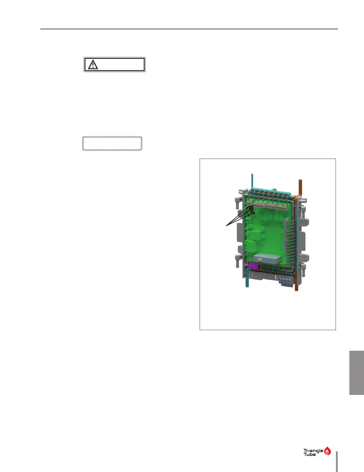
8.1.2 Fuse Locations
• The CTRLMax control module contains 3 internal
replaceable 5A fuses as shown in Fig. 29 below.
• The top two fuses protect the INSTINCT as well as
the CH, DHW, and Flame outputs.
• Spare fuses are located on the back of the control
module enclosure.
• A 2.5A fuse is also located on the terminal strip, to
protect the output. Refer to Fig. 32 on page 48.
Fig. 29 - CTRLMax Control Module Fuse Location
Location of fuses
 Loading...