48
CHAPTER 8
CHAPTER 8 - WIRING
8.2. External Wiring
8.2.1 General Requirements
All eld wiring must comply with:
• National Electrical Code (ANSI/NFPA 70) for installa-
tions in the U.S., and any other national, state, pro-
vincial or local codes or requirements.
• Canadian Electrical Code Part 1 (CSA C22.1) for in-
stallations in Canada.
ELECTRICAL SHOCK HAZARD. For your safety,
disconnect electrical power supply to the unit
before servicing or making any electrical con-
nections to avoid possible electric shock hazard.
Failure to do so can cause serious injury, or death.
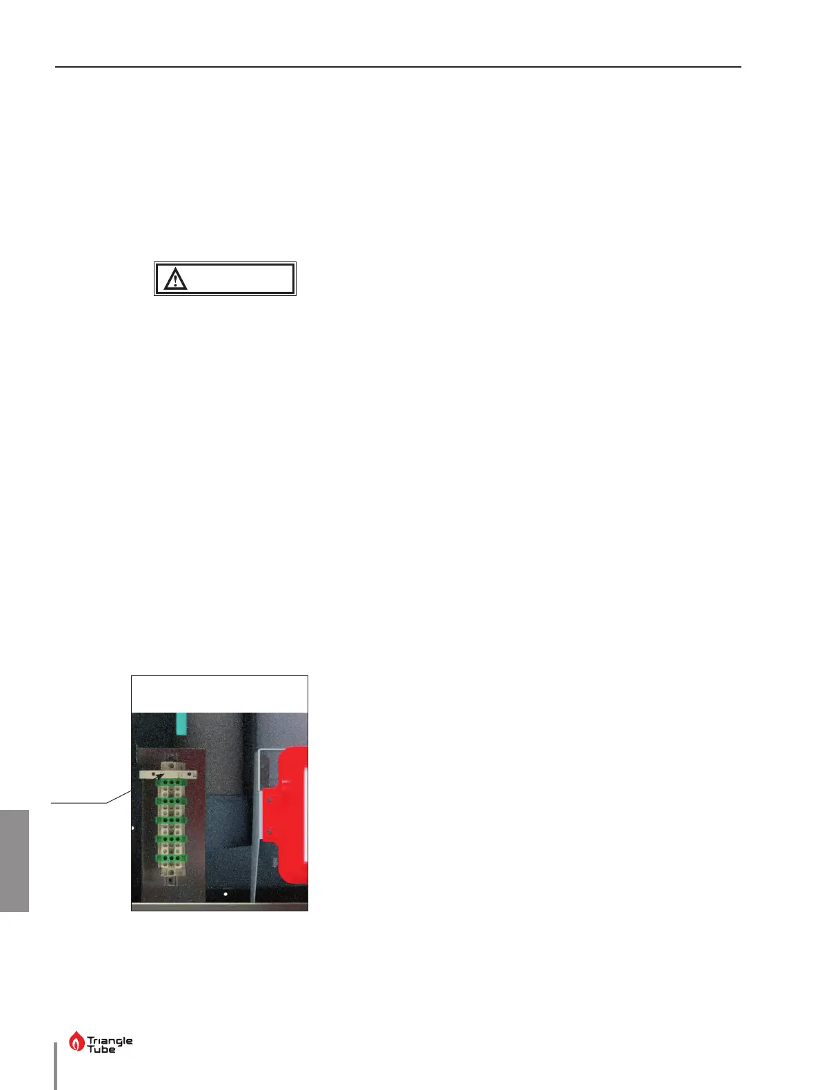
The low voltage terminals are located at the
bottom of the CTRLMax control module. The
line voltage terminals are located in the lower
left corner as shown in Fig. 21 below.
8.2.2 Line Voltage Connections
1. Connect a dedicated 120 VAC/15A service to the
line voltage terminals located internally in the low-
er left corner, as shown in Fig. 32 below.
2. Route the incoming 120 VAC power wires through one
of the provided openings in the bottom jacket panel.
3. The unit is provided with a service switch located
on the front panel, check local code requirements
for compliance.
WARNING
NOTICE
If local electrical codes require an additional service
switch, the installer must provide and install a fused
disconnect or minimum 15 amp service switch.
8.3. External Wiring - INSTINCT Solo Units
8.3.1 Circulator Wiring
1. The circulator connections used will depend on the
systems piping layout. See Fig. 17 on page 31
and Fig. 18 on page 32 for common system pip-
ing applications and associated circulator wiring.
Consult the Fig. 10 on page 20 and the INSTINCT
CTRLMax Control Supplement for additional op-
tions.
The circulator output is protected by fuses on
the CTRLMax control module. The total com-
bined amp draw of the CH, DHW, and Flame
outputs must not exceed 4 amps at any time
for the INSTINCT 110 and 155 units, or 3 amps
at any time for the INSTINCT 199 units. Use an
isolation relay to lower the total combined amp
draw if exceeding this limits.
2. Connect the CH circulator wiring to the line voltage
terminals located internally in the lower left corner, as
shown in Fig. 32 on the left. This circulator is typically
used to supply heat to the central/space heating loop.
3. Connect the DHW circulator wiring to the line volt-
age terminals located internally in the lower left
corner, as shown in Fig. 32 on the left. This circulator
is typically used to supply heat to an indirect hot
water heater.
4. Connect the system pump wiring to the line volt-
age terminals located internally in the lower left
corner, as shown in Fig. 32 on the left.
NOTICE
NOTICE
Fig. 32 - Terminal Strip Location
2.5A Fuse
 Loading...