49
CHAPTER 8
CHAPTER 8 - WIRING
8.3.2 Low Voltage Connections
Line and Low Voltage wiring should be separated to
prevent possible electrical noise on the low voltage
circuits. Line and Low Voltage wiring should use sepa-
rate electrical knockouts on the INSTINCT cabinet and
should remain separated inside the INSTINCT.
CH and DHW call connections to the IN-
STINCT require a dry contact with no external
voltage present. Ensure no external voltage is
present on each set of wires before connecting
to the INSTINCT. If external voltage is present,
the use of an isolation relay is required to pre-
vent damage to the CTRLMax controller.
8.3.3 Thermostat Wiring
The CTRLMax control has two thermostat call inputs for
multiple zone / temperature systems. This allows each
call to have its own outdoor reset curve and maximizes
the eciency of the system.
Simultaneous CH1 and CH2 calls will result
in the INSTINCT operating at the highest target
temperature.
NOTICE
NOTICE
8.3.4 Outdoor Sensor Wiring
The Outdoor Reset function and Warm Weather Shut-
down (WWSD) features require the connection of the
included outdoor temperature sensor. See Chapter 12
on page 75 for outdoor sensor installation and setup.
8.3.5 Domestic Hot Water Wiring
The Domestic Hot Water terminals can accept either a
call from an aquastat (thermostat) or temperature sen-
sor. Use of the included indirect water heater sensor is
recommended.
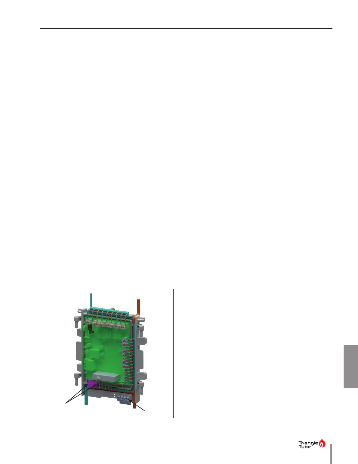
1. Connect the DHW aquastat or temperature sensor
wires to low voltage terminals X4-1&2 located at the
bottom of the CTRLMax control module as shown
in Fig. 33 on page 49.
8.3.6 Additional Boiler Limits
Additional boiler limits (High Temperature Limit, LWCO,
etc.) can be wired into either the Manual Reset Limit or
Auto Reset Limit terminals of the INSTINCT. These lim-
it connections will provide a “hard” lockout requiring a
manual reset of the INSTINCT or a “soft” lockout in which
the INSTINCT will automatically reset when the limit re-
sets.
A Manual Reset External Limit Open (E87) lockout will
occur anytime the manual reset terminals are open. An
Auto Reset External Limit Open (76) lockout will not oc-
cur until just before ignition when the auto reset termi-
nals are open. The Auto Reset terminals should be used
for any type of burner interlock such as a combustion air
louver or water ow proving switch.
• The Manual Reset Limit and Auto Reset
Limit terminals are located on the lower
right corner of the CTRLMax control mod-
ule housing.
• Manual Reset Limit and Auto Reset Limit
connections to the INSTINCT require a dry
contact with no external voltage present.
Ensure no external voltage is present on
each set of wires before connecting to the
INSTINCT. If external voltage is present, the
use of an isolation relay is required to pre-
vent damage to the CTRLMax controller.
NOTICE
Fig. 33 - Low Voltage Connections
Low voltage
connections
External limit
Terminals
 Loading...