NORMAL.DOT Gespeichert in:G:\Support\Dokumentationen_CDs\8003Speedy\Service Manual\Servicemanual 8003.doc Gespeichert am:2003/03/10
max Version 14
Seite 65 von 87
I N D I V I D U A L M A R K I N G S Y S T E
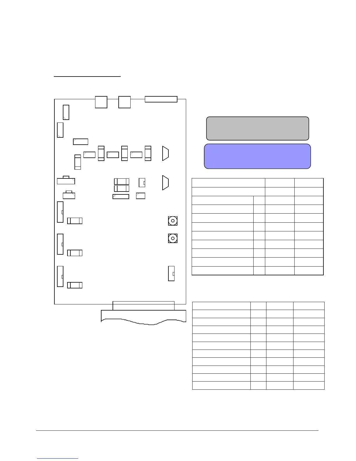
Connector Assignment
X13
X11
X12
X14 X15 X16
X23
X24
X9
X8
X7
X20
X2
F4
F5
F10
F1 F2 F3
CPU
X19
X28
X3
X4
X18 X17
X5
X22
X21
Netzspannung:
Hauptsicherungen
Relais-Einschaltkreis
Kühlventilatoren-Laser
Luftkompressor
Gravurraum-Beleuchtung
interne DC-Versorgung
interne DC-Versorgung
230 VAC 115 VAC
F10
F1
F2
F3
F4
F5
2 x 6,3 AT 2 x 10 AT
200 mAT 200 mAT
1 AT 2 AT
2 AT
2 AT
2 AT
2 AT
2 AT
2 AT
1 AT
1 AT
Sicherungen im Power-Laser Pro
ACHTUNG: Sicherungen nur durch solche vom
ACHTUNG: Vor dem Öffnen des
Gehäuses Netzstecker ziehen.
1
1
11
1 1
1
1
1
1
gleichen Wert und Typ ersetzen !
F9
F8
F7
6,3 AT
6,3 AT
6,3 AT
6,3 AT
6,3 AT
6,3 ATF7
F8
F9
DC-Versorgung X-Achse
DC-Versorgung Y-Achse
DC-Versorgung Z-Achse
Fuses in the Power Laser Pro
Mains voltage 230 VAC 115 VAC
Main fuses 2 x 6.3 AT
2 x 10 AT
Relay F10 200 mAT 2oo mAT
Cooler fans - Laser F1 1 AT 2 AT
Air compressor F2 1 AT 2 AT
Illumination Engr. Area F3 1 AT 2 AT
Internal DC supply F4 2 AT 2 AT
Internal DC supply F5 2 AT 2 AT
DC supply X axis F7 6.3 AT 6.3 AT
DC supply Y axis F8 6.3 AT 6.3 AT
DC supply Z axis F9 6.3 AT 6.3 AT
Caution Replace fuses only with the same value and type
CAUTION: Before opening the
system unplug the mains
 Loading...