21
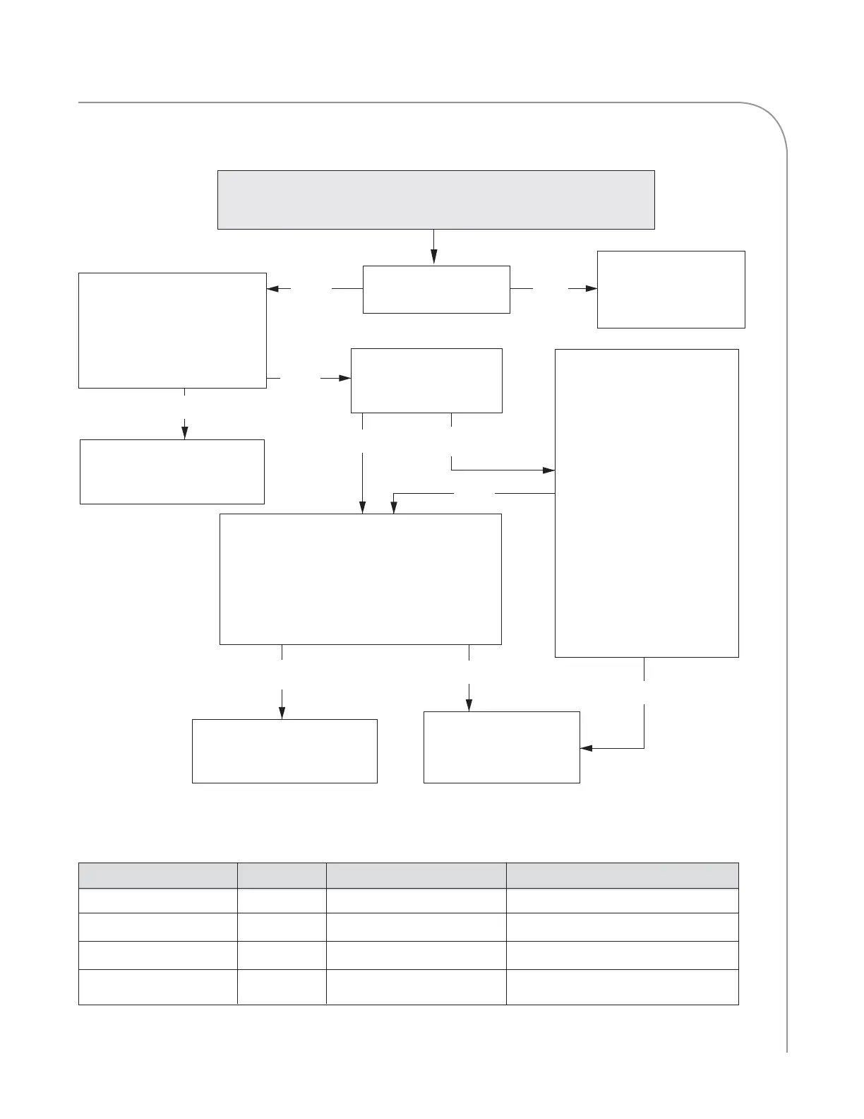
TROUBLESHOOTING
To From Description Expected Resistance
Black Red Winding (A-B) 2.0-2.6 Ohms
Black White Winding (A-C) 2.0-2.6 Ohms
Red White Winding (B-C) 2.0-2.6 Ohms
Black, Red or White Green Windings to Chassis Open
Figure 21: Motor Windings Resistance Table
Troubleshooting:
F1-1: BLOWER (Top Oven)
F1-2: BLOWER (Bottom Oven)
YES
YES
NO
Check the wire harness and
if necessary, replace blower
motor.
Remove obstruction
or if necessary, replace
blower motor.
Do the resistance measure-
ments between windings and
chassis agree with values on
motor windings resistance
table (below)?
Is the blower motor
spinning freely?
NO
YES
1. Locate and disconnect
the 6-pin minifit Molex
connector (see page 41
for schematic).
2. Disconnect the QC-11
Connector.
3. Ground pin 5 of the
connector to the
chassis. Observe status
indicator on the display.
Does the “A” backlight
disappear when pin 5 is
grounded?
NO
NO
Is Status Indicator “A”
backlit on the Service
Screen? (page 16)
YES
Check the wire harness
and if necessary, replace
the control board.
1. Test pin 1 of QC-11 connector for
control voltage.
2. Ground one lead and insert other into
pin 1 of the QC-11.
Is 0-10 VDC present throughout all speed
settings in Test Mode?
Check the wire harness and
if necessary, replace BMSC.
NO
YES
 Loading...