22
TROUBLESHOOTING
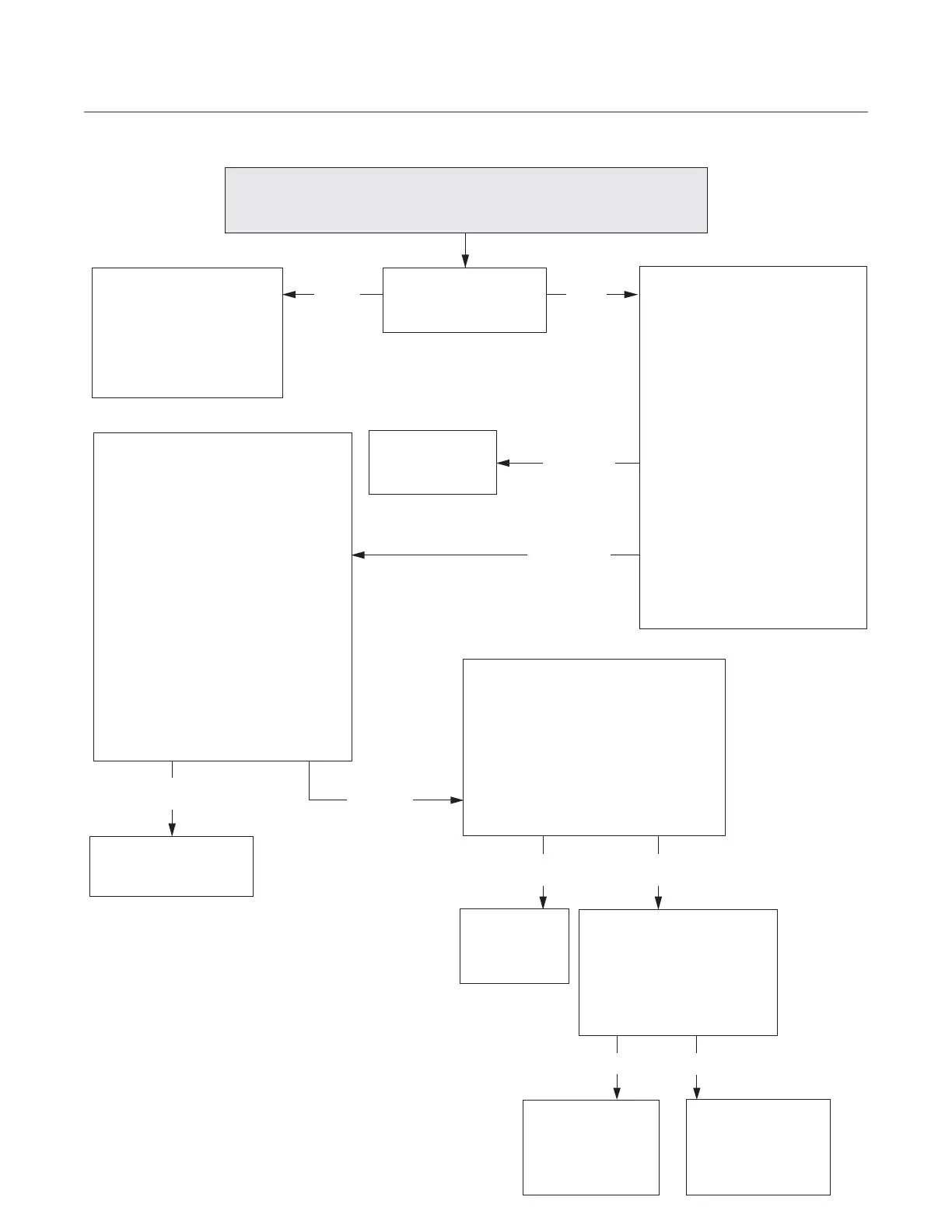
Troubleshooting:
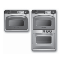
F2-1: LOW TEMP (Top Oven)
F2-2: LOW TEMP (Bottom Oven)
YES
Replace the
defective heater.
Replace the solid state
relay.
NO
SSR is defective
Replace the I/O
control board
(SAGE).
Correct wiring.
YES
NO
Reset and determine why
it tripped – excess grease
buildup, etc. The reset
button is on the back panel
near the power cord.
Is the high-limit
thermostat tripped?
Is wiring from the solid state relay
to the I/O control board OK?
Check wires at the 4-pin connector
on the SSR:
(A + - + - B)
1 2 3 4
(See page 41 for schematic.)
Ensure wiring is
correct. If neces-
sary, replace the
defective RTD.
SSR OK
YES
NO
Is each RTD functioning
properly? (See page 36)
Is the solid state relay defective?
1. Leave the 4-pin control wiring
connected.
2. Set the meter to DCV.
3. On the service screen, turn on one
of the cavity heaters (page 16).
4. On K5/K6, check between B(-)
white to ground. If the signal goes
from 24 VDC to 0.VDC, then the
signal is good and the SSR is
defective.
5. Repeat steps 3-4 for the other
cavity heater on K4 between A(-)
white to ground.
Heater is
defective
Is there a defective heater?
1. Isolate the heater circuits by
disconnecting them from the
respective high-limit switch
and K9 relay.
2. Each cavity has two heaters
which can be tested indepen-
dently. Only two out of four
heaters can be tested simul-
taneously in Test Mode. Each
heater should have a resistance
of 17 Ohms at room
temperature.
See page 16 for Service Screen
instructions.
Heater OK
 Loading...