9
5.2 Analog Board ANL-T2
The analog board contains the drivers of the valves, heaters and pump. It
contains the sensors circuits connected to the control system, and serves
as a junction to the autoclave connections.
The input is 12VDC & 5VDC and the output is for all the signals to the
autoclave.
— The power supply provides the DC voltages 12V and 5V through the
connector JP3 to the board and further to the DIG-T2 board.
— The computer is connected to the board through the connector P1, by
RS232 interface.
— The analog and digital inputs, from the temperature sensor, electrode
door switch, etc. are connected through connector JP6, the
conversion circuits of the sensors are located on this board.
— The pressure sensor MPX2200 that measures the chamber pressure is
connected to the board through connector JP8, to the conversion
circuit of the sensor that is located on this board.
— The analog to digital conversion circuit A/D (U5) and the analog
multiplexer (U6) for 8 analog inputs (temperature, pressure, and
electrode) are located on this board and transfer digital signal to the
DIG-T2 board.
— All the drivers and power circuits to the solenoids (valves, door
locking) are included on this board.
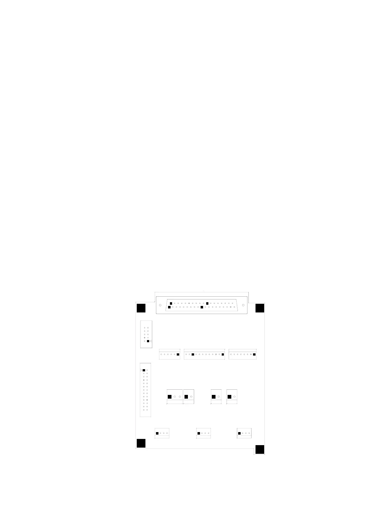
Layout diagram of the ANL-T2 is provided below.
ANL - T2 BOARD
JP6
1211
1
JP11
1
JP2
37
19
JP7
20
1
JP9
1
PLUG
JP1
JP5
JP3
ANL T1 BOARD
JP4
1
P1
JP10
1
1
JP12 JP8
1
1


 To Next Page