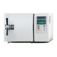
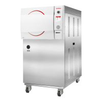
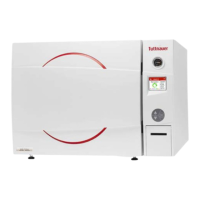
7
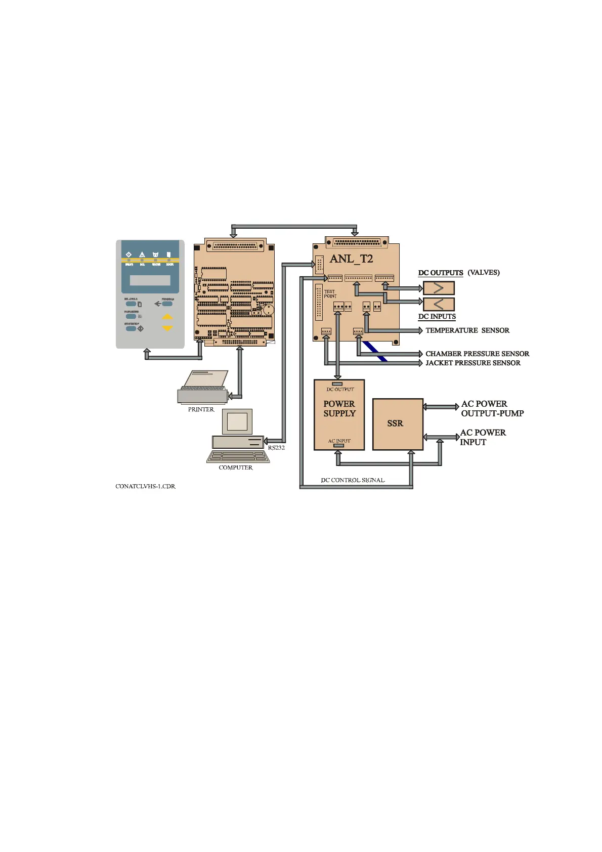
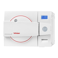
5. DESCRIPTION OF THE CONTROL SYSTEM.
(See CDR Control diagram).
The control system is based on 3 electronic boards designed according to the
autoclave requirements, the digital board DIG-T2 containing the micro-
controller memories, buffers and digital ICs and the analog board ANL-T2
which performs the processing of signals coming from the sensors and switches.
The AC-T1 board consists of filters and AC drivers. DC voltages 12V and 5V,
supplied by a switching type power supply, powers the 3 electronic boards.
CONTROL SYSTEM BLOCK-DIAGRAM
The system is provided with communication interfaces RS 232 to PC and to
parallel printer.
5.1 Digital Board DIG - T2
— The digital board is connected to the keypad panel, to the parallel
printer and to the analog board ANL-T2.
— The board contains the micro-controller (U15) type 80C32 that runs
the software program of the system.
— On the board, are three types of memories:
1) EPROM memory (U17), part no. 27512 storing the program
codes.
2) RAM memory (U21) with a capacity of 32KB for the temporary
data during the running of the program.
3) EPROM memory (U22) that is a fixed serial memory with an
electrical writing and erasing.
— This EPROM serves as a non-volatile memory, enabling the system
to change follow-up tables during running of program codes, and
ensuring this data is not lost in case of power failure.
DS1
BZ1
97-05
C22
2
DIG T3
1
JP1
D1
RP1
U18
U8
C2
C3
C4
8
1
JP3
R4
U3
Q1
R2
U4
U19
U1
R1
20
19
R3
C16
Y1
C15
R9
U14
U11
37
1
SKT
U17
U16
U12
C17
U21
C9
C7
C6
C5
U15
+
+
DIG-T2 BOARD
34
33
C24
C23
U22
C25
37
19
20
1
PLUG
JP1
1
JP8
1
JP12
1
JP9
1
JP3
1
JP10
1
JP6
1
JP7
P1
12
1
JP5
JP2
1
JP4