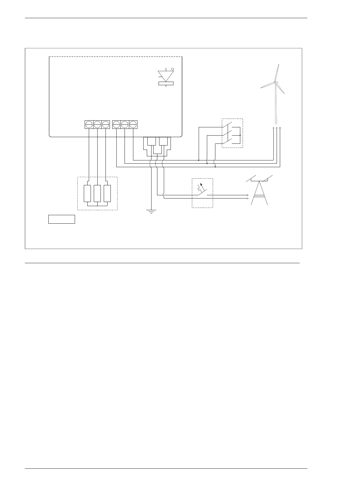
Fig. 5.1. Power circuits wiring diagram for PS100-WT inverter
When connecting a three-phase permanent magnet generator, the following sequence should be followed:
1. Switch On the Emergency STOP.
2. Unscrew the inverter cover by 4 screws.
3. Connect the generator wires to GENERATOR terminal strip.
4. Connect the generator load resistors to RESISTOR terminal strip.
5. Be sure that there is no dangerous voltage on wires(!) and then connect to L,N,PE terminal strip the
electrical line.
6. Switch On the power from public electric side.
7. Set the inverter parameters: load characteristic in group 3, breaking parameters in group 10, the
point of start and stop of generator in parameters: 2.1, 1.20 i 1.21. Detailed description is placed in
chapter 8.
8. Refasten the inverter cover by four screws.
9. Switch OFF the Emergency STOP.
10. Wait a while to ensure that inverter did not signal the fault.
24 PS100 – User manual