Chapter 9. Digital inputs and outputs
9.2. Anemometer
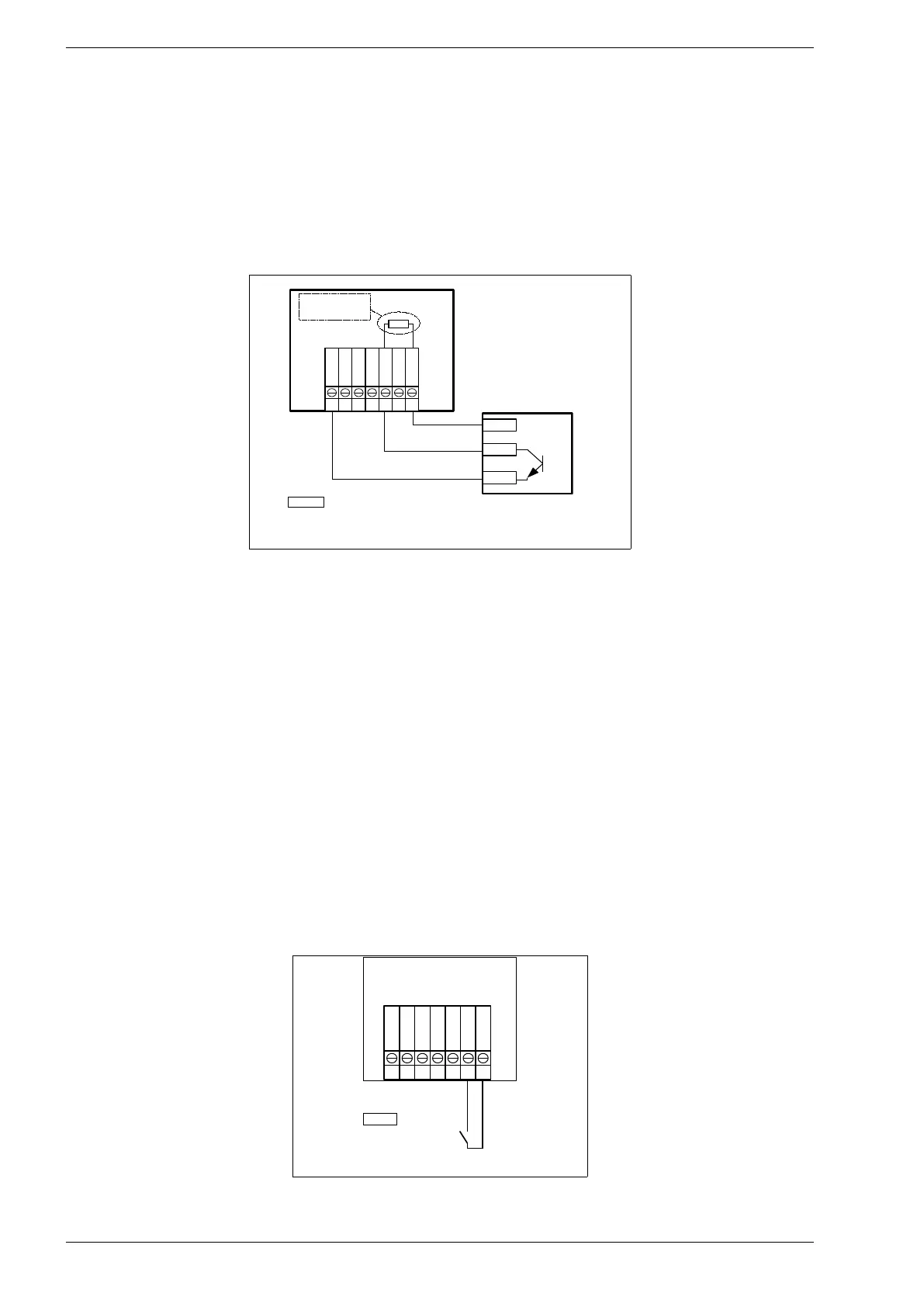
The inverter works with anemometer with open collector type (OC) output or reed relay output. The
maximum frequency must be less than 1 kHz. It is possible to get a supply voltage to anemometer from the
5Vdc output, provided that the maximum load current of 50mA is not exceeded. Fig. 9.3. Wiring diagram of
the anemometer shows the connection diagram of the anemometer on the example of the Fardata NP-3.
In order to correctly measure the wind speed, it is necessary to enter wind speed [m/s] corresponding to 10
pulses / second in parameter 10.6. This value is given by the manufacturer of the anemometer (ex. 1.5). The
current wind speed is showed in par. 0.31.
Fig. 9.3. Wiring diagram of the anemometer
9.3. Storm Protection
In our inverter we have a storm protection. Users are able to set dedicated parameters for the storm
protection. Storm protection system works through these parameters:
• P. 10.48 In this parameter users could set maximum velocity of wind for the storm protection
threshold.
• P. 10.49 In this parameter users could set time of storm protection threshold.
When the system detect above velocity than set, K3 contactor turning off and dump load is turning on. When
the set time up, storm protection getting deactivated and process repeats to check wind velocity. If wind
velocity still above of the storm protection threshold, system repeats same process.
9.4. Remote Output Stop Order
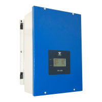
User could connect and use an external switch to control inverter. Switch must be connected to DI_1(6) and
5VDC sockets(7).
• When the switch is open; inverter works.
• When the switch is close; inverter stops, K3 contactor switching off, output relays switching off and if
the inverter is for the wind turbine, dump load is switching on.
Fig. 9.4. Remote stop of the inverter