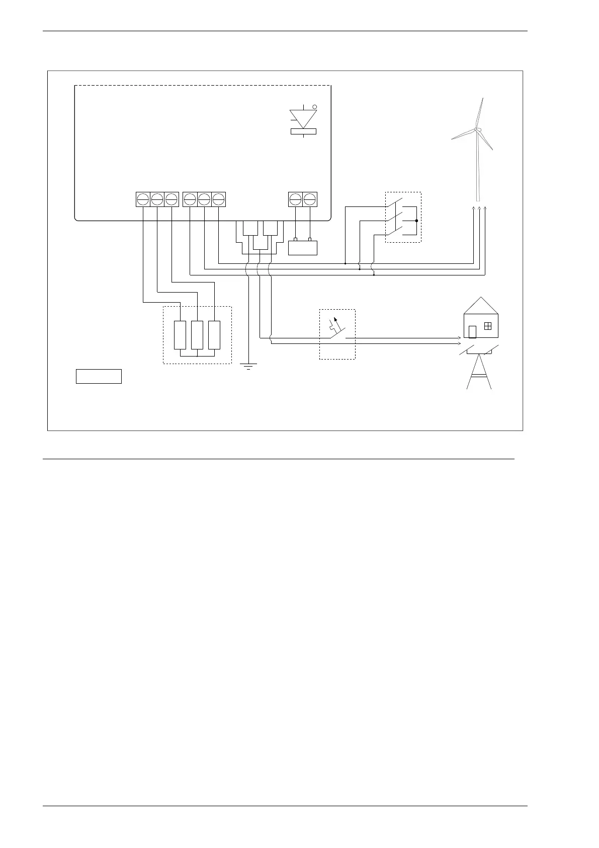
Fig. 6.1. Power circuits wiring diagram for PS100-WT+BC inverter
When connecting a three-phase permanent magnet generator, the following sequence should be followed:
1. Short the generator windings through an external emergency stop.
2. Remove the 4 screws securing the inverter cover.
3. Connect the generator cables to the terminals described GENERATOR.
4. Connect the leads of the generator braking resistors to the terminals described RESISTORS
in emergency situations.
5. Connect electrical loads to terminals L, N, PE.
6. Connect the earth electrode to the PE terminal and connect the N and PE terminals together.
7. Connect the battery observing the safety rules described in section 12 Battery charger module on page
49.
8. Set operating mode 0: "Off-grid" or 2: "auto on-off-grid" in parameter 1.1.
Note: for operation in mode 2: "auto on-off-grid" it is required to connect the PS100-INT module.
9. Set the system parameters: load characteristics in group 3, braking parameters in group 10 and specify
the generator's starting and stopping load in parameters: 2.1, 1.20 and 1.21. A detailed description of
the inverter operation can be found in chapter 8.
10. Screw the inverter cover.
11. Turn off the generator emergency stop.
12. Wait a moment to check that the device is not detecting a failure.
28 PS100 – User manual