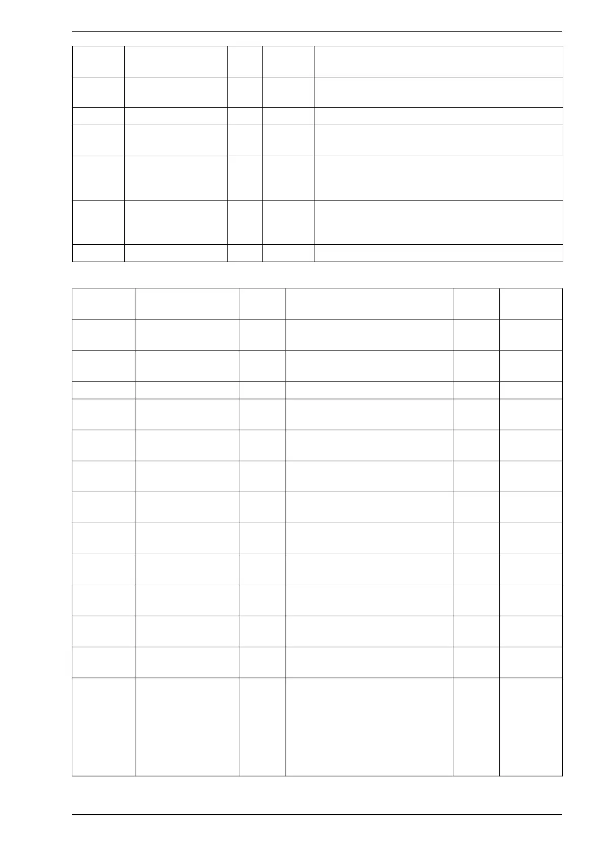
Chapter 13. Groups of parameters
Param.
No.
Name Unit
Access
level
Description
11.20 Reconn.PowerRamp 2 Time after reconnection in which the power limit at the
inverter output increases from 0 to the nominal power
11.21 StartingPowerRamp 2 Power rise time from 0 to nominal power
11.22 ReducePowerFreq 2 Grid frequency threshold at which the inverter output
power limit is enclosed
11.23 OverFreqDroop 2 The percentage decrease in the inverter output power
limit as the grid frequency increases above the
response threshold
11.24 CosPhi 2 Specifies the output current power coefficient ( cosφ)
and type reactive power (capacitive / inductive)
generated by the inverter
11.25 Rocof Ramp 2 Rocof protection value
GROUP 12 – EN50549 Grid parameters
Param.
No.
Name
Access
level
Description
Default
setting
Setting
range
12.01 Rated network
voltage for protection
2 Rated voltage 230 V 100-400V
12.02 Rated frequency for
protection
2 Rated frequency 50 Hz 50Hz, 60Hz
12.03 Nominal Power Rated power Pn -
12.04 UnderVoltage St1 2 Threshold undervoltage protection
threshold 1
0.85 0.2..1.00
12.05 UnderVoltage St1
Time
2 Threshold undervoltage protection
threshold 1 - time
1.2 s 0.1..100.0 s
12.06 UnderVoltage St2 2 Threshold undervoltage protection
threshold 2
0.4 0.20..1.00
12.07 UnderVoltage St2
Time
2 Threshold undervoltage protection
threshold 2 - time
0.20 s 0.10..5.00 s
(ch:0.05s)
12.08 OverVoltageSt1 2 Overvoltage protection threshold -
level 1 (instantaneous)
1.15 1.00..1.20
12.09 OverVoltageSt1Time 2 Overvoltage protection tripping time
- level 1
0.1 s 0.1..100.0 s
12.10 OverVoltageSt2 2 Overvoltage protection threshold -
level 2 (instantaneous)
1.15 1.00..1.30
12.11 OverVoltageSt2Time 2 Overvoltage protection tripping time
- level 2
0.10 s 0.10..5.00 s
(ch.: 0.05s)
12.12 OverVoltage10min 2 10-minute overvoltage protection
threshold (delayed)
1.10 1.00..1.15
12.13 Enable ST1
Under/Over Freq
Selection of active security
thresholds:
0 – St2
1 – St1
2 – DI4
3 – Remote
0 0, 1, 2, 3
PS100 – User manual 63