Chapter 7. Built-in control panel
7. Built-in control panel
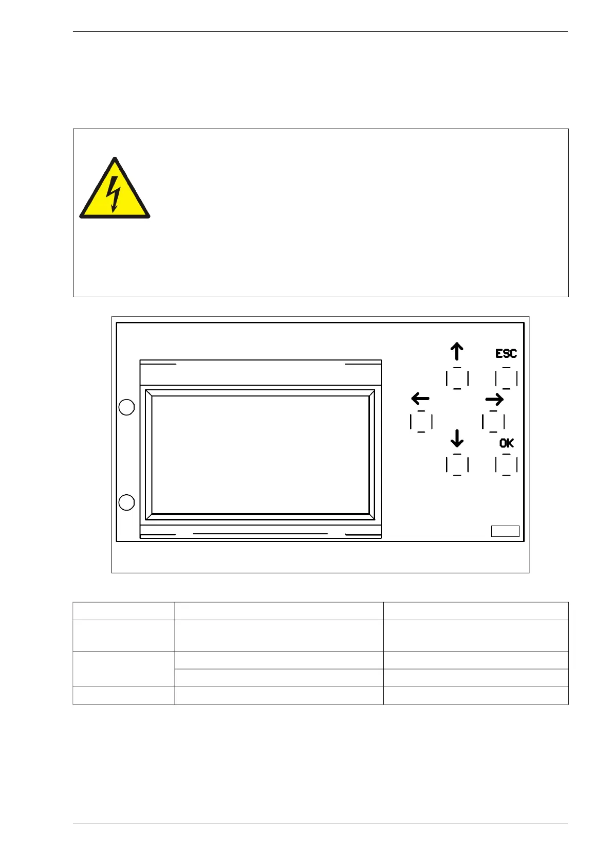
After turning the system on, it will initialize and the screen will take its initial state: basic view. Access to the
keys is obtained after removing the front cover of the inverter. The <OK>, <ESC>, <up>, <down>, <right>
and <left> keys are used to navigate the menu and to change parameter settings – see chapter 7.2.
Warning!
Be especially careful due to the possibility of electric shock!
Access to the control panel is obtained after removing the front cover of the
inverter. After disassembling the front cover of the inverter, at the same
time, access to elements that are, under the conditions of normal inverter
operation, under the electrical voltage dangerous to life and health (active
parts) is obtained.
Removing the front cover of the inverter (when the electric voltage is supplied to the
device both from the network side and the generator side) and changing the settings can
only be made by a person with appropriate electrical qualifications.
Fig. 7.1. Control panel
Table 7.1. Status diodes
Diode colour Type of light Description
None
LEDs off, the display shows basic
information
Too low inverter input power, inverter in
energy saving mode
Green
Flashing light Inverter is ready to work
Continuous light Inverter is working
Red Continuous light Fault
PS100 – User manual 31