Chapter 9. Digital inputs and outputs
9. Digital inputs and outputs
The inverter has 5 digital inputs 5Vdc, R
IN
> 300Ω and 3 relay outputs with 2A switching power 230Vac. On
the digital inputs terminal block there is also 5Vdc voltage terminal available to operate digital inputs and any
external devices with a maximum current consumption of 50mA.
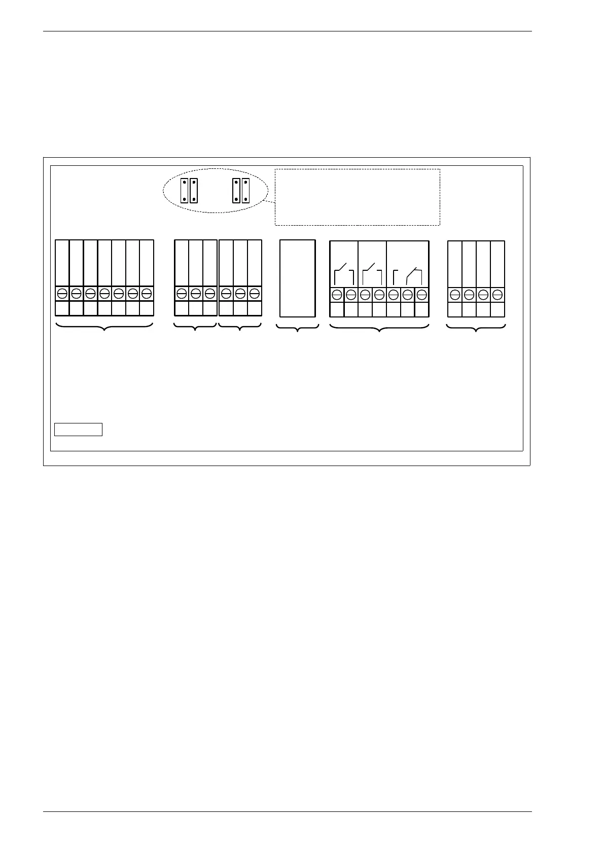
Fig. 9.1 shows the view of the terminal blocks on the PS100-WT inverter. To view the status of digital inputs
and outputs enter the I/O PREVIEW in the MAIN MENU of the inverter.
Fig. 9.1. Digital inputs and outputs terminals -PS100
By default the inverter uses three relay outputs K1, K2, K3 to adjust the frequency of the generator if the
wind turbine is equipped with a tail and digital input DI_2 for operating an optional anemometer
(anemometer) - see chapter 9.2 Anemometer on page 42.
40 PS100 – User manual
1
GND
2
DI_5
3
DI_4
4
DI_3
5
DI_2
6
DI_1
7
5VDC
1
B(-)
2
Z3
3
GND
4
B(-)
5
A(+)
6
GND
1 2 3 4 5 6 1
IN_A
2
OuA
3
5VDC
4
AGND
ETHERNET
K3
K1
K2
Z4
Z1
Z2
Jumpers Z1...Z4 should be
closed if the inverter is the last
one on communication bus.
Digital inputs
D1...D5
Output 5Vdc
(max. 50mA)
Modbus RTU
- only for service
purposes
A(+)
Modbus RTU
– for general uses
Relay outputs
K1...K3
(max. 2A
230Vac)
Analog In/Out
- only for service
purposes
Ethernet network
ps100-14-2-en
7