Chapter 3. Specification
3. Specification
3.1. Technical data
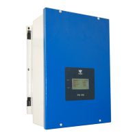
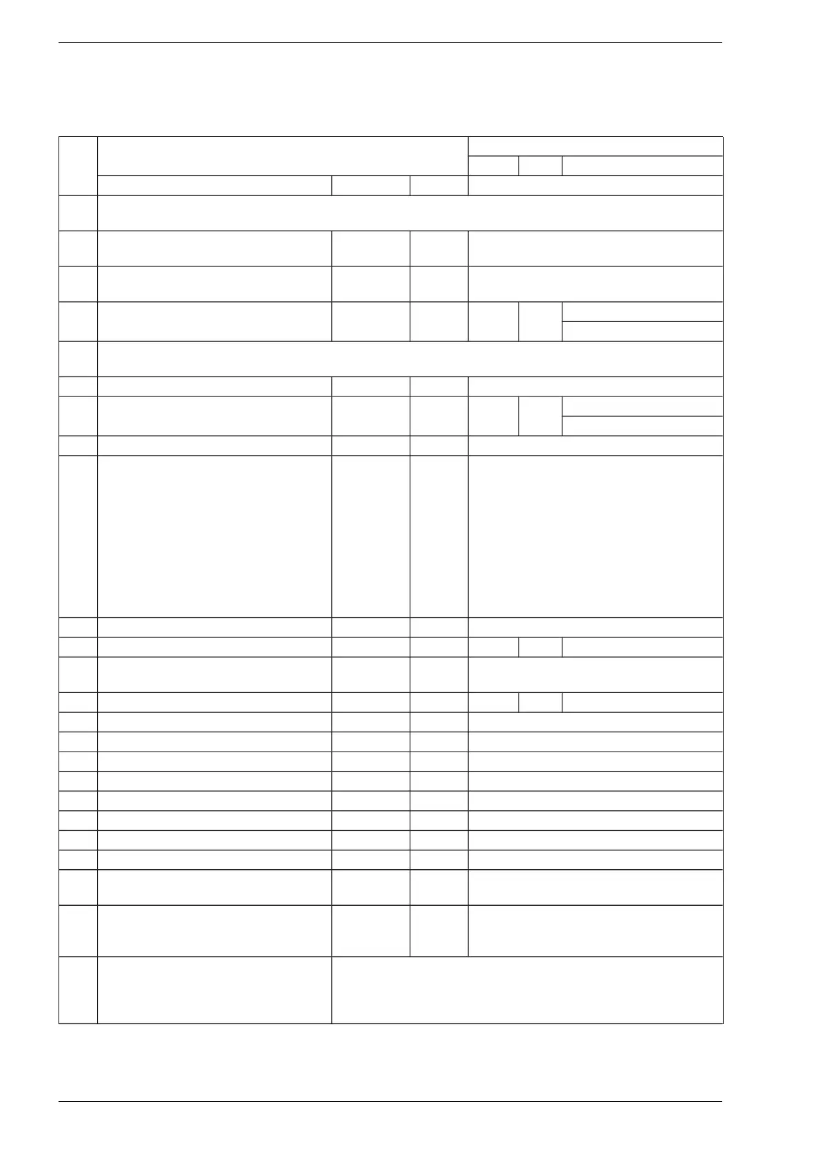
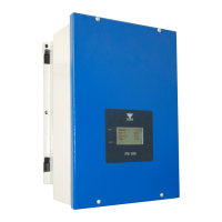
Table 3.1. PS100 inverters technical data
Type PS100
No. 1kW 3kW 5.5kW
Description Name Unit
1 WT input (AC voltage): permanent magnet synchronous generator
PS100-WT, PS100-H inverters
1.1 Working voltage range
from the AC generator side
Ugen V 3 x 60..290 V AC
(Phase - Phase)
1.2 Rated voltage from the AC generator
side
Ugen-n
(n* nominal)
V 3 x 230 V AC
1.3 Maximum input current
from the AC generator side
Igen-max A 7A 13A PS100H/5.5kW: 13A
PS100WT/5.5kW: 24A
2 PV inputs (DC voltage): photovoltaic panels
PS100-PV, PS100-H inverters
2.1 Voltage range from the PV side Upv V 60..450 V DC
2.2 Maximum current of PV panels Ipv-max A 9A 13A PS100H/5.5kW: 13A
PS100PV/5.5kW: 2x13A
2.3 Type of PV connector - - MC4
3 Number of PV and WT inputs - pcs. PS100-PV/1kW, PS100-PV/3kW:
1 x PV input - PV1
PS100-PV/5.5kW:
2 x PV input - PV1, PV2
every input has individual MPPT
algorithm
PS100-WT/xkW:
1 x WT input
PS100-H/xkW:
1 x PV(PV1) input + 1 x WT input
4 Efficiency (at rated output power) ƞ % 97%
5 Nominal AC output power Pn kW 1 3 5.5
6 Output voltage
(from the power grid side)
Uout V 1 x 230V, 50Hz
7 The maximum output current Iout A 4,5 13 25
8 Current THD % < 3
9 Work modes - - On-Grid, Off-Grid
10 Nominal voltage of DC-link circuit Udc V 380V
11 Maximum voltage of DC-link circuit Udc-max V 600V
12 Transistors switching frequency fsw kHz 16
13 Maximum temperature of heatsink Trad-max
o
C 85
14 Communication - - Ethernet, RS485
15 Digital inputs DI1..DI5 pcs. 5
16 Relay outputs: 2A 230V AC K1
K2, K3
pcs. K1: Switchable, 2A 230V AC
K2, K3: Normally Open, 2A 230V AC
17 Internal relays controlling the
operation of braking resistors
Inverters PS 100-WT and PS100-H
Rezystory - 30 A, AC1
18 Protections - before run-up the PMSG,
- before too high device temperature,
- the monitoring system of the power grid parameters
8 PS100 – User manual