Ubee Interactive Understanding the Device Rear Panel
Ubee DDW3611 Wireless Cable Modem Gateway Subscriber User Guide • November 2012 5
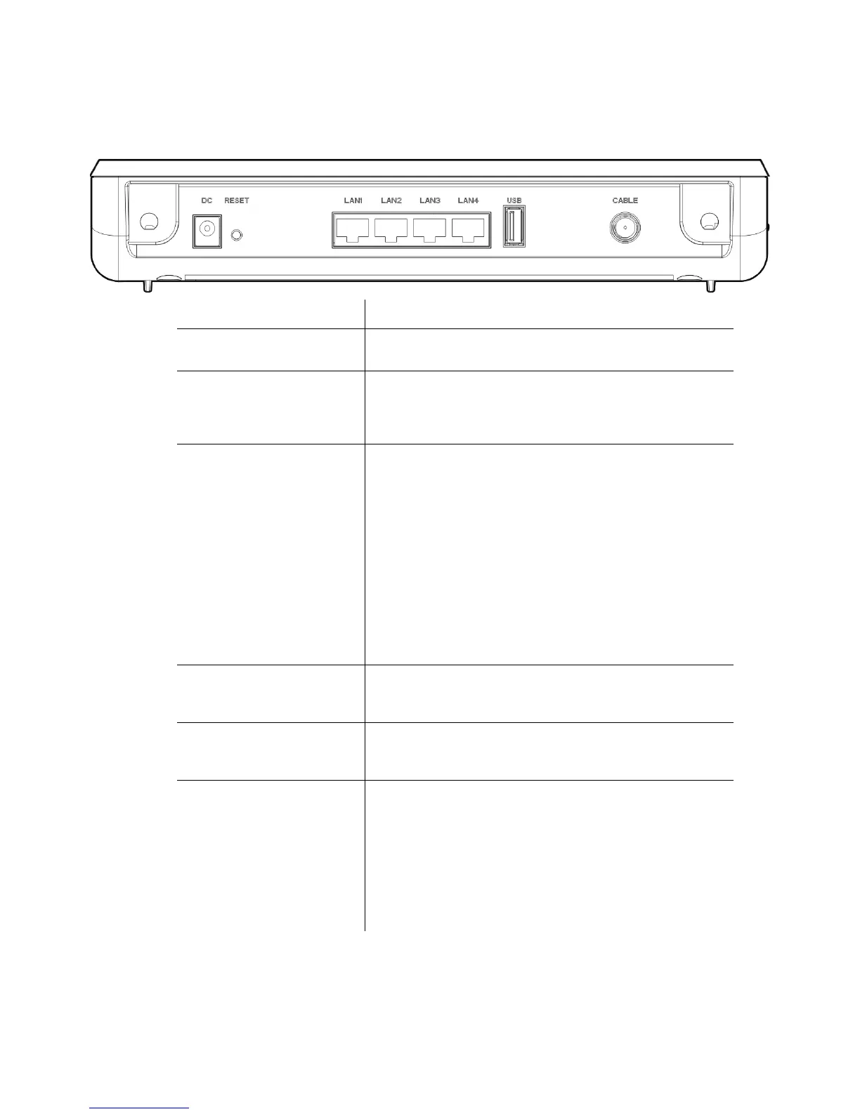
1.5 Understanding the Device Rear Panel
Review the following image and descriptions of the rear panel connections on the device.
Item Description
DC Connects the power adaptor to the device. Use only the
power adaptor provided with the DDW3611.
RESET Restores the default settings of the device including wireless
and custom gateway settings. Use a pointed object to push
down the reset button for 5-10 seconds until the power LED
turns off. After the power LED turns off, release the button.
LAN1
LAN2
LAN3
LAN4
Connects the device to local area network (LAN) Ethernet
devices such as computers, gaming consoles, and/or
routers/hubs using an RJ45 cable. Each LAN port on the
back panel of the device has an LED on the front of the
device to indicate its status when an Ethernet device is
connected.
When an Ethernet device is connected to the cable modem:
LED is Green when connected at 10/100 Mbps speeds.
LED is Blue when connected at 100/1000 speeds
(Gigabit Ethernet).
LED blinks when data is passed between the cable
modem and the connected device.
USB Connects to some USB devices, such as computers and flash
drives if the USB connector is supported/enabled by the
service provider.
CABLE Connects to the cable outlet (with the cable provided by your
service provider), or a cable splitter connected to the cable
outlet.
WPS Connects a PIN-protected Wi-Fi device to the cable modem
when the Wi-Fi Protected Setup method is used. When the
WPS button is pushed or triggered through the device’s Web
GUI, an LED on the front of the device blinks for four minutes
until a PIN is entered from the wireless client, such as a
laptop computer, that wants to connect. After a Wi-Fi client
attaches successfully, the LED remains on for five minutes,
and then turns off. Refer to Understanding the Wireless Menu
on page 57 for more information.