40
2.4. Control Box Electrical IO
This chapter explains how to connect devices to the electrical I/O outside of the
control box.
The I/Os are extremely flexible and can be used in many different devices, including
pneumatic relays, PLCs, and emergency stop buttons.
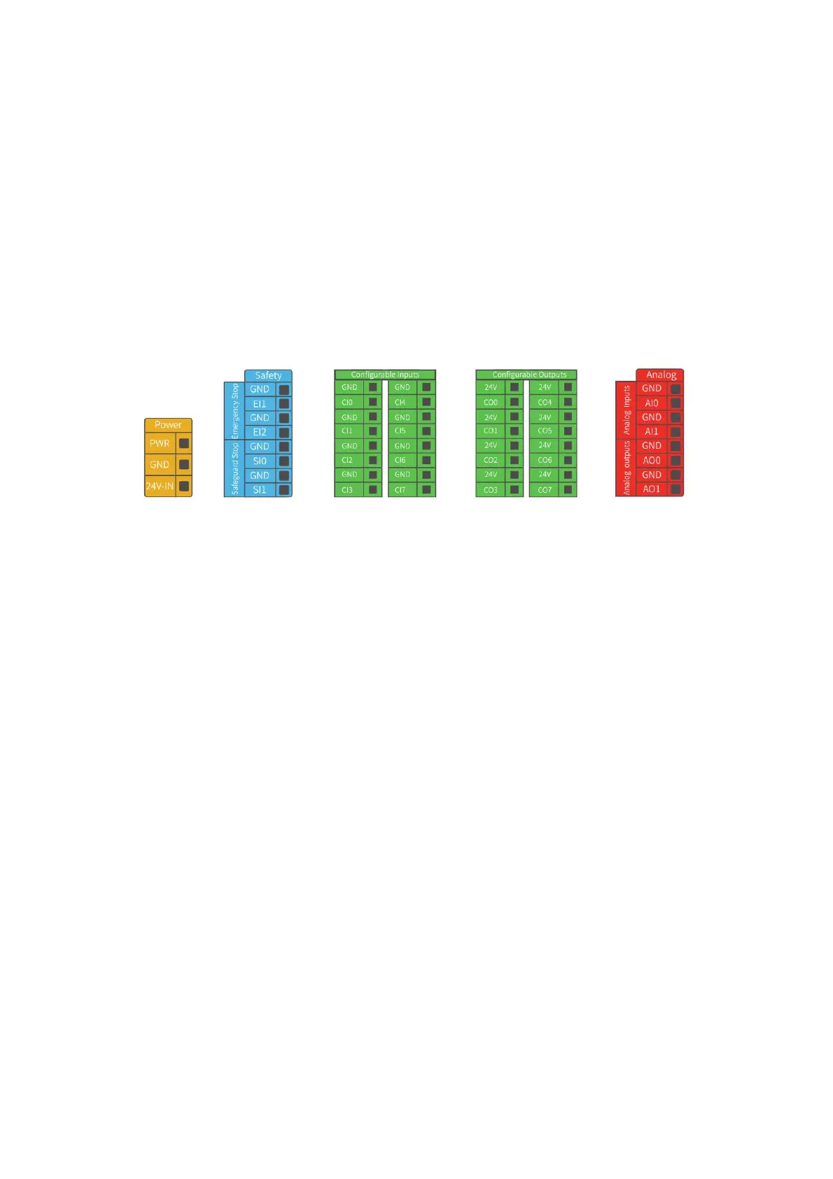
The figure below shows the electrical interface layout inside the control box.
2.4.1. General Specifications for all Digital I/O
This section describes the electrical specifications for the following 24V digital I/Os
for the Control Box.
• Dedicated safety I/O.
•
Configurable common I/O.
It is very important to install xArm according to the electrical specifications.
All the I/O must comply with the specifications. The digital I/O can be powered by a
internal 24V power supply or by an external power supply by configuring the power
junction box. In the following figure, PWR is the internal 24V power output. The
lower terminal (24V-IN) is the 24V input external power input for I/O. The default
configuration is to use internal power, see below.
 Loading...