- 47 -
7
0
m
m
I
N
D
O
O
R
O
U
T
D
O
O
R
O
U
T
D
O
O
R
S
E
N
S
O
R
R
E
F
R
I
G
E
R
A
N
T
E
L
E
C
T
R
I
C
A
L
D
R
A
I
N
A
G
E
C
A
B
L
E
L
IN
E
S
C
A
B
L
E
T
U
B
E
1
0
m
m
.
M
in
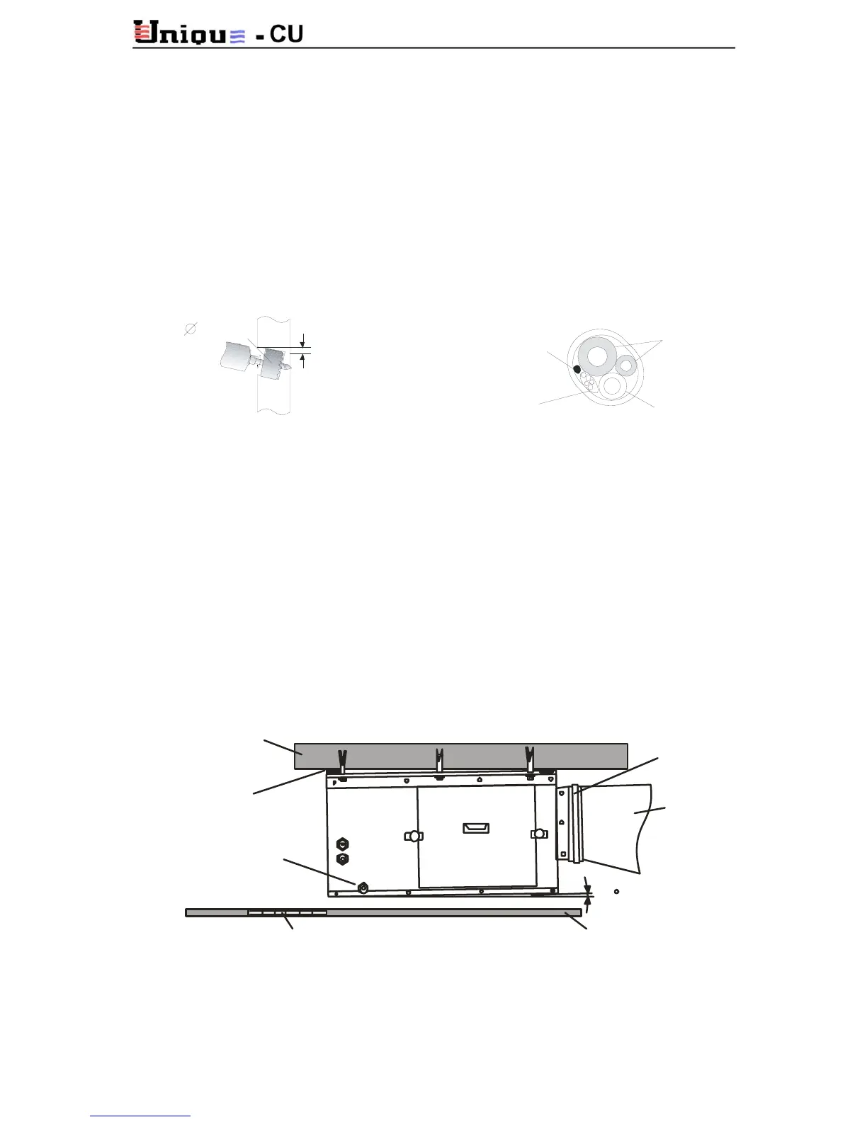
7.6.3 Drilling a Hole in the Wall for Drainage and Inter-Unit Connections
• To make the connections between the indoor and outdoor units, a 70 mm hole should
be drilled for the refrigerant lines, drainage hose and electrical cable passage, through
the wall, as shown in Figure 7-6.
• Make sure to drill outwards and downwards, so that the opening in the outside wall is
at least 10 mm lower than the opening on the inside.
• Route the drainage hose at the bottom of the hole.
• Fill in the remaining gap with an appropriate sealant.
Fig. 7-6
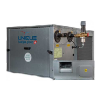
7.7 Air Duct Installation
• The air ducts should be constructed of 0.7-0.8 mm galvanized metal sheet.
• To obtain optimal results, duct cross sections, connections, elbows and branches must
be properly designed. We highly recommend seeking for expert advice on this matter.
• Air ducts should be properly insulated (preferably on the inside) with 50 mm thick
fiberglass insulation having density of at least 24 Kg/m
3
.
• See Figure 7-7 for general guidelines.
Fig. 7-7
CONCRETE
SLEEVE
AIR DUCT
RUBBER
DRAIN HO SE
AIR INTA KE G RILL C EIL IN