- 51 -
8. INSTALLING THE CONTROL SYSTEM AND CONNECTING POWER
8.1 Identification of the Components
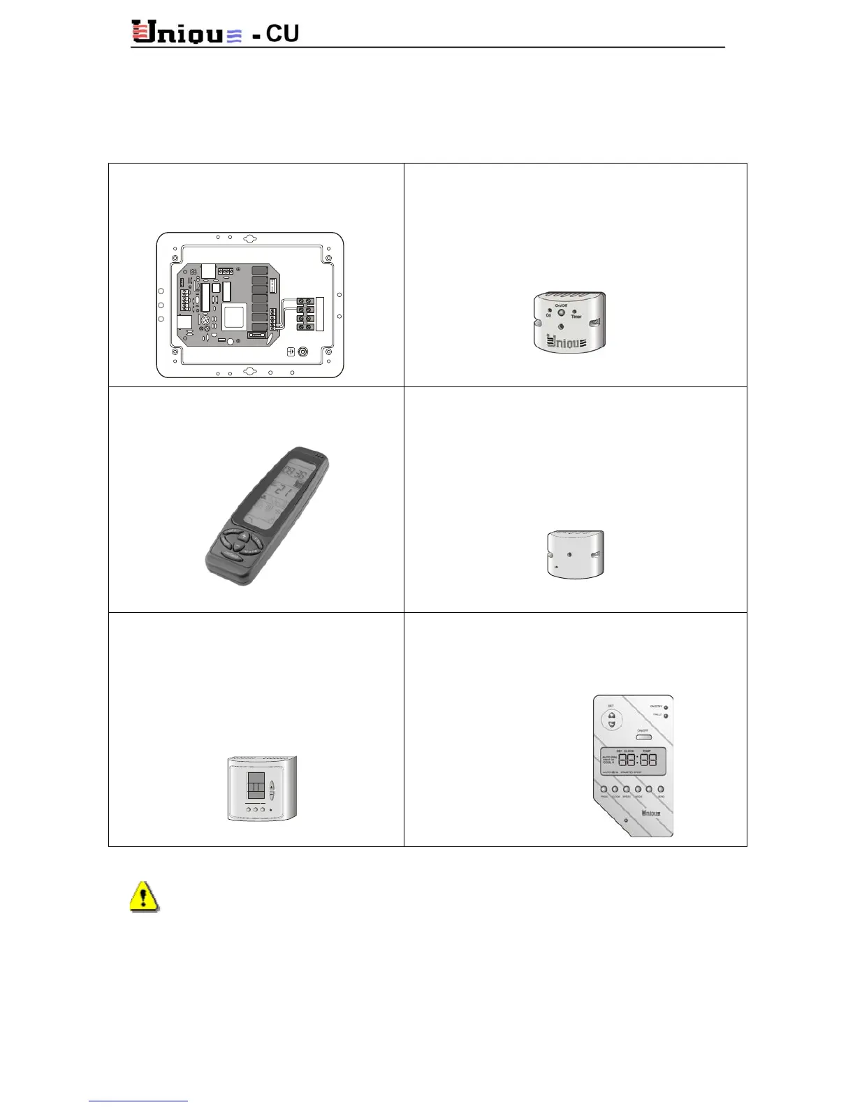
MIG 101:
Main control box.
Standard supply for all units.
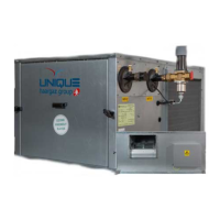
M101P:
I/R (Infra Red) Receiver Panel, wall mounted.
Features I/R receiving and On/Off pushbuttons.
Standard supply for all units that do not have the
wall mounted thermostat ETN1000.
RT-01:
I/R Transmitter (Remote Control).
Daily programmable.
IRR/1:
I/R Room Receiver, wall mounted.
Enables the use of the Remote Control unit from
another room.
Up to 10 Room Receivers can be daisy chained.
Optional supply.
ETN1000:
Wall mounted thermostat.
Features local temperature readout and
adjustment, on/off pushbuttons, mode
adjustment, fan adjustment and I/R
receiving.
Optional Supply.
MIGA2400:
Programmable wall mounted thermostat.
Same features as ETN1000 but with additional
weekly programming capabilities.
Without I/R receiving.
Optional supply.
Important! The control wires between the main control box and the wall mounted
thermostat utilize low voltage 12V DC.
The control wires must run in separate tracks, at least 50 mm away from high
voltage cables (230 or 400 Volts).
Avoid also proximity to communication cables or RF interference. The use of
shielded cables is recommended in such locations.
N
T1T1
N
C
T2
14
HI
RV
T2
15
MEF1
T3
16
LO
F2
T3
17
L3 L2 L1 N