Page 2-7
Operation and Specifications 2.5 - Maintenance
MX15/19
B
Y
T
RUCK
Maneuver the work platform into transport position and chock the wheels. Secure the work plat-
form to the transport vehicle by attaching chains or straps of adequate load capacity to the Tie
Down/Lifting D-Rings.
2.5 M
AINTENANCE
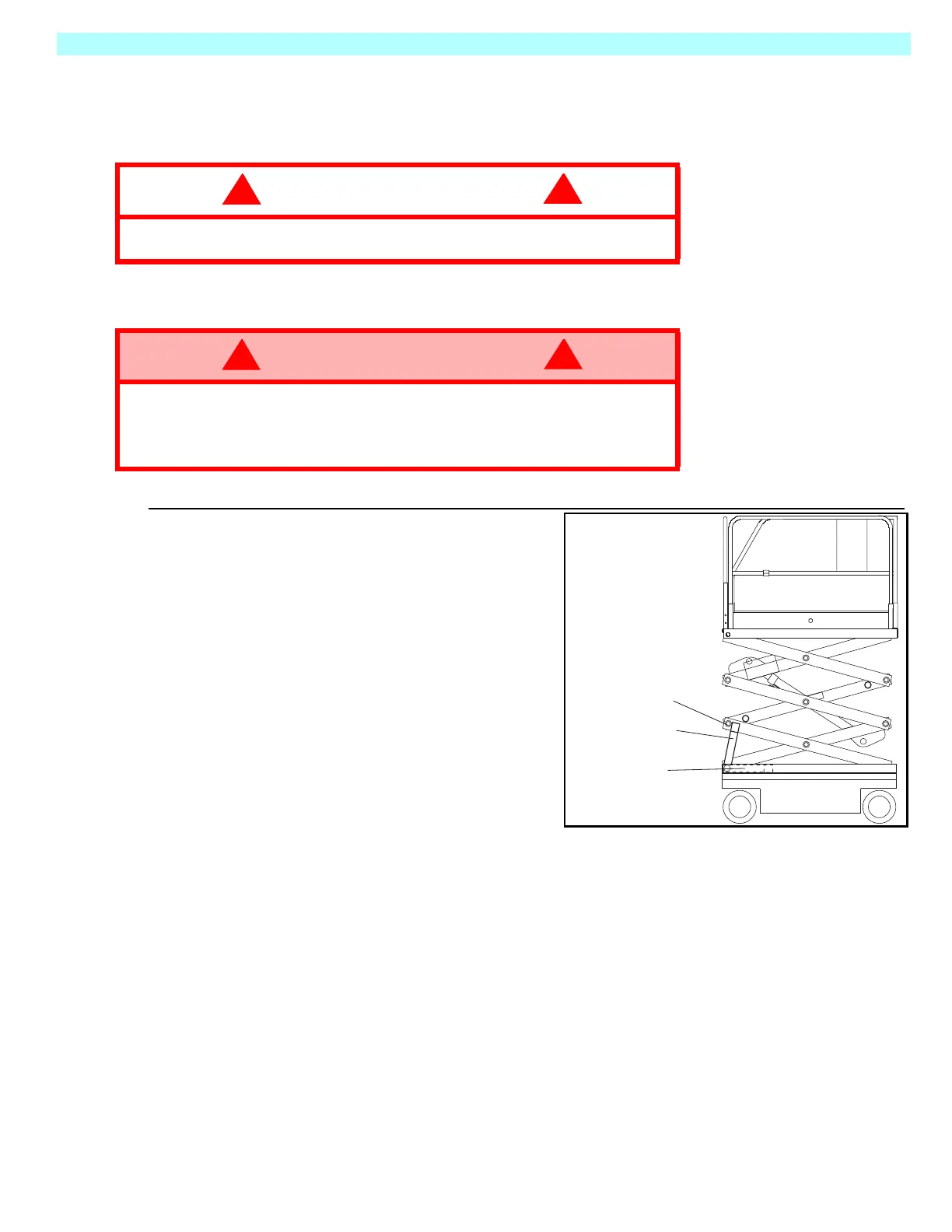
Figure 2-7:
Scissor Brace
B
LOCKING THE
E
LEVATING
A
SSEMBLY
SCISSOR BRACE INSTALLATION
1. Park the work platform on a firm, level
surface. Completely unload the plat-
form before installing the Scissor
Brace.
2. Verify that the Chassis and Platform
Emergency Stop Switches are ON by
pulling each button out.
3. Turn and hold the Chassis Key Switch
to CHASSIS. Push the Chassis Lift/
Lower Switch to UP and elevate the
platform approximately 7 ft. (2.1 m).
4. Rotate the Scissor Brace to a vertical
position.
5. Carefully lower the platform until the end of the Scissor Arm Weldment rests on the Brace.
S
CISSOR
B
RACE
S
TOWAGE
1. While holding the Brace, slowly raise the platform, using the Chassis Controls until the end
of the Scissor Arm Weldment clears the Scissor Brace.
2. Rotate the Scissor Brace forward to rest on the Chassis.
3. Push the Chassis Lift/Lower Switch to LOWER and completely lower the platform.
CAUTION
!
!
Overtightening of the chains or straps attached to the Tie Down/Lifting D-
Rings may result in damage to the work platform.
WARNING
!
!
Never perform service while the platform is elevated without first blocking the
elevating assembly.
DO NOT stand in the elevating assembly area while deploying or storing the
brace.
Brace Installed
Scissor Arm
Weldment
Brace Stowed
 Loading...


